Operator operation detection device
A technology for operating elements and operation detection, applied in the direction of instruments, electroacoustic musical instruments, etc., can solve the problems of unstable contact state of contacts, and achieve the effect of suppressing vibration and maintaining stability.
- Summary
- Abstract
- Description
- Claims
- Application Information
AI Technical Summary
Problems solved by technology
Method used
Image
Examples
no. 1 approach >
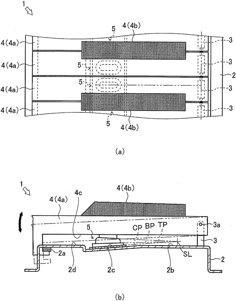
[0032] Below, use figure 1 , the keyboard device 1 according to one embodiment of the present invention will be described. The keyboard device 1 is a keyboard device of an electronic keyboard instrument in this embodiment.
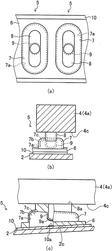
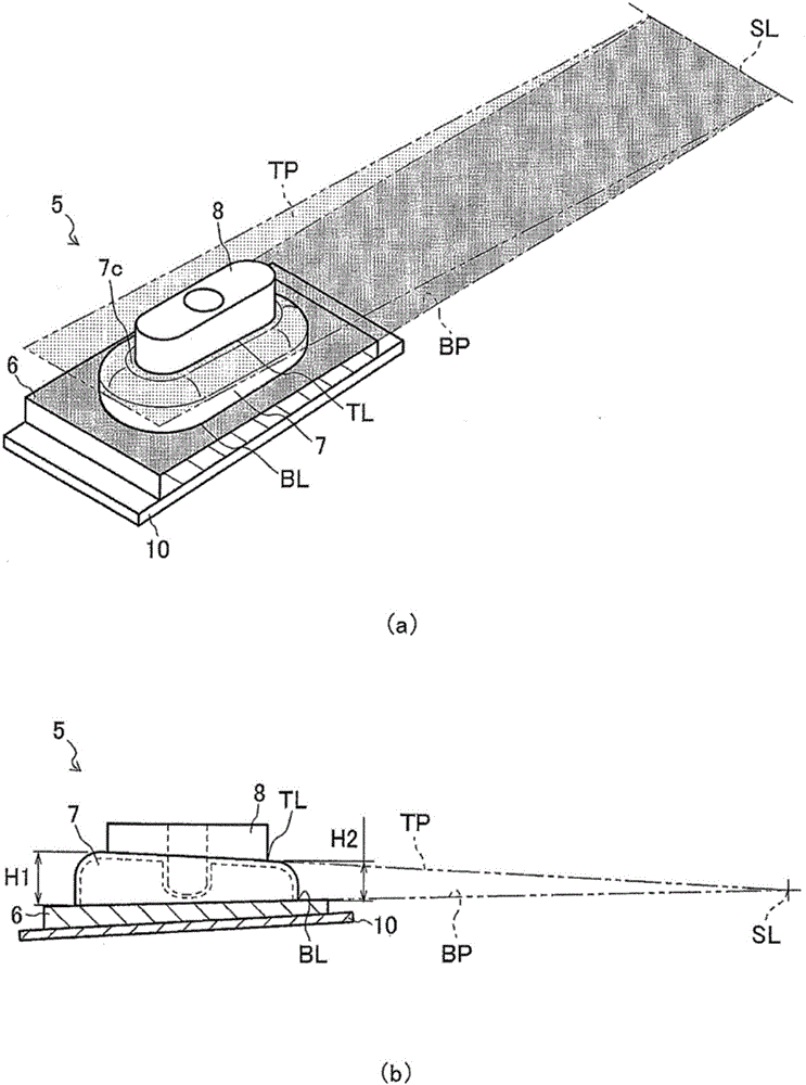
[0033] The keyboard device 1 includes a frame (machine base) 2, an upper limit stopper 2a, a key fulcrum portion 3, a key 4, and a key operation detection device 5 which is an operating element operation detection device. In the keyboard device 1 , a plurality of keys 4 (white keys 4 a and black keys 4 b ) are arranged adjacent to each other on a frame 2 which is a machine base. One side of each key 4 is rotatably supported on the key fulcrum portion 3 provided on the frame 2 via the pivot point, that is, the rotating shaft 3a. touch. Moreover, in the keyboard device 1, a plurality of key operation detection devices 5 corresponding to each key 4 are provided in a manner opposite to each key 4, that is, in the keyboard device 1, the keys 4 and the key op...
no. 2 approach >
[0059] Next, use Image 6 , the key operation detection device 11 which is the second embodiment of the operation element operation detection device of the present invention will be described. It should be noted that the key operation detection device 11 of this embodiment is figure 1 In the shown keyboard device 1, a device suitable for replacing the key operation detection device 5, by using figure 1 , figure 2 The same parts are indicated by the names, reference numerals, and reference signs used in the description thereof. In the following embodiments, specific descriptions of points that are the same as those in the already described embodiments will be omitted, and differences will be centered. illustrate. The key operation detection device 11 is a device that generates a reaction force against the operation of the key 4, which is an operating element, and transmits a signal corresponding to the operation of the key 4. , a top portion 8, an inner raised portion 12, ...
no. 3 approach >
[0066] Next, use Figure 7 , the key operation detection device 13 which is the third embodiment of the operation element operation detection device of the present invention will be described. It should be noted that the key operation detection device 13 of this embodiment is figure 1 In the shown keyboard device 1, a device suitable for replacing the key operation detection device 13 or the key operation detection device 11 is used. figure 1 , figure 2 Names, reference numbers, and reference signs used in their descriptions. The key operation detection device 13 is a device that generates a reaction force against the operation of the key 4, which is an operating element, and transmits a signal corresponding to the operation of the key 4. 9. The base plate 10, the raised portion 14, the top portion 15, and the base plate 10 made of an insulator base material.
[0067] Such as Figure 7 As shown, the arch portion 14 is formed in a hollow arch shape that bulges from the ot...
PUM
 Abstract
Description
Claims
Application Information
 - R&D
- Intellectual Property
- Life Sciences
- Materials
- Tech Scout
- Unparalleled Data Quality
- Higher Quality Content
- 60% Fewer Hallucinations
Browse by: Latest US Patents, China's latest patents, Technical Efficacy Thesaurus, Application Domain, Technology Topic, Popular Technical Reports.
© 2025 PatSnap. All rights reserved.Legal|Privacy policy|Modern Slavery Act Transparency Statement|Sitemap|About US| Contact US: help@patsnap.com


