Clockwise and counterclockwise rotation switching device for power tool

A technology of electric tools and switching devices, which is applied in the direction of electromechanical devices, portable motorized devices, manufacturing tools, etc., can solve the problems of contact pressure reduction, achieve the effects of improving contact life, avoiding cost increases, suppressing vibration and welding

Inactive Publication Date: 2009-03-04
MAKITA CORP
View PDF1 Cites 2 Cited by
  • Summary
  • Abstract
  • Description
  • Claims
  • Application Information

AI Technical Summary

Problems solved by technology

However, if it is used near the upper limit of the elastic range in order to increase the abutment pressure, the elastic end 4a will be plastically deformed due to the influence of heat and vibration, resulting in a decrease in the abutment pressure, causing chattering (chattering) of the elastic end 4a. ) or deposited

Method used


Image

  • Clockwise and counterclockwise rotation switching device for power tool
  • Clockwise and counterclockwise rotation switching device for power tool
  • Clockwise and counterclockwise rotation switching device for power tool

Examples


no. 1 approach

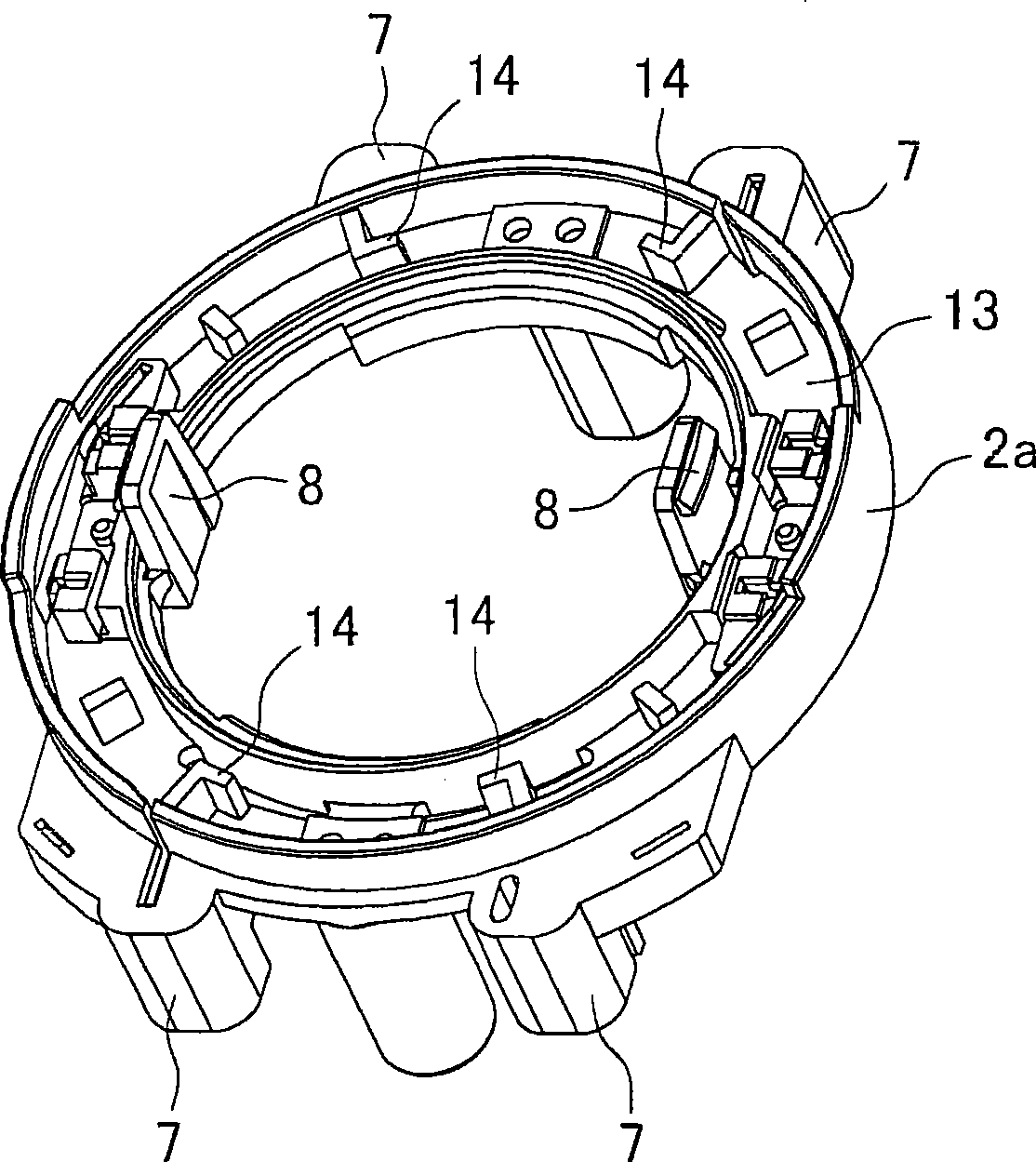
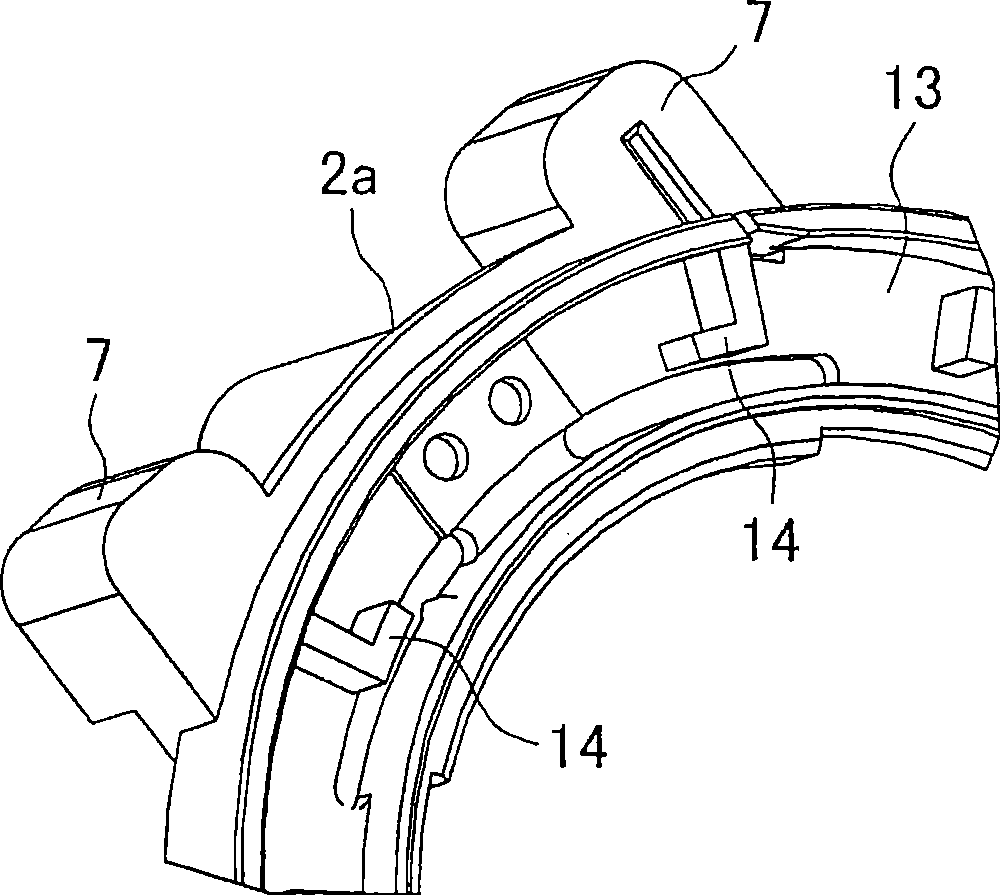
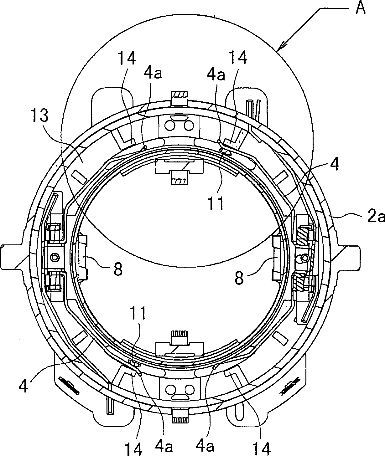
[0024] Figure 1A and Figure 1B It is an explanatory diagram of a component base (a state where a fixed contact is not attached) 2a used in the forward and reverse switching device of the present invention, Figure 1A represents a stereogram, Figure 1B Indicates a partially enlarged view. Figure 2A and Figure 2B is an explanatory diagram of the component base 2a in a state where the fixed contacts are mounted, Figure 2A for top view, Figure 2B An enlarged view of part A. In this component base 2a, there are a pair of fixed contacts 4, 4 in a point-symmetrical planar arc shape, etc. Figure 6 , Figure 7 , Figure 8A and Figure 8B The component base 2 described in is the same, but on the bottom plate 13 of the component base 2a of the present invention, on the outer peripheral side of each elastic end 4a of the fixed contact 4, integrally protrudingly provided with L-shaped as a restricting portion when viewed from above. Limit protrusions 14 . When the movable...

no. 2 approach

[0028] Figure 3A and Figure 3B It is also an explanatory diagram of the component base 2b in the state where the fixed contact is not installed, Figure 3A represents a stereogram, Figure 3BIndicates a partially enlarged view. In the member base 2b, a through hole 15 is provided at the front end of the regulating protrusion 14 on the bottom plate 13, so that the leading end of the regulating protrusion 14 is provided with elasticity.

[0029] Therefore, by the forward and reverse switching device, the brush base 3 is rotated to the forward rotation position, the movable contact 11 is in contact with the elastic end 4a of the fixed contact 4, and the elastic end 4a is flexibly deformed to the outer peripheral side so as to contact the regulating protrusion. 14 abutment, at this time, if Figure 4 As shown, the lower end of the regulating protrusion 14 flexibly deforms toward the outer peripheral side due to its elasticity, and presses the elastic end 4 a toward the movab...


PUM


Abstract

The invention provides a clockwise and counterclockwise rotation switching device of a power tool capable of effectively suppressing chattering or fusing of an elastic end to improve contact durability. An end part of a fixed contact 4 is formed to be an elastic end 14 deformed by contacting to a movable contact 11. A unit base 2a includes a regulation projection 14 which is abutted with the elastic end 4a, which is deformed in contact with the movable contact 11, so as to regulate the deformation quantity.

Description

technical field [0001] The invention relates to a forward and reverse switching device provided for switching the rotation direction of a motor in a motor-driven electric tool. Background technique [0002] The forward and reverse switching device of the electric tool includes a component base and an annular brush base. The component base is fixed on the stator of the motor in the housing and has a pair of fixed contacts electrically connected to the stator coils respectively. The brush base is rotatably installed on the component base, and holds a pair of carbon brushes facing the commutator and in sliding contact. moving contacts. By rotating the brush base, the state of contact between the two movable contacts and the fixed contacts can be switched, whereby forward rotation and reverse rotation of the motor can be selected (for example, refer to Patent Document 1). [0003] Figure 6 It is an exploded perspective view showing a specific example of the forward and revers...

Claims


Application Information

Patent Timeline
Patent Type & Authority Applications(China)
IPC IPC(8): B25F5/00H01H1/50H01H3/16
CPCH02K5/148H02K23/18H01H9/063H02K23/66
Inventor 吉川修二
Owner MAKITA CORP
Why Eureka
Try Eureka