Web drying apparatus and web drying method

a technology of web and drying apparatus, which is applied in the direction of web processing, drying machines with progressive movements, thin material processing, etc., can solve the problems of disturbed airflow in an area, achieve the effect of suppressing the disturbance of airflow, and suppressing the flutter of the web

Active Publication Date: 2020-09-17
DAINIPPON SCREEN MTG CO LTD
View PDF0 Cites 1 Cited by
  • Summary
  • Abstract
  • Description
  • Claims
  • Application Information

AI Technical Summary

Benefits of technology

[0006]The present invention is intended to solve the above problem, and it is an object of the present invention to make it possible to suppress flutter of web in the vicinity of an opening due to an effect of exhaust by an exhaust part provided between a blow-drying part and an opening of a housing while drying the web by injection of gas from the blow-drying part.
[0009]In the present invention (the web drying apparatus, the web drying method) having such a configuration, the rectifying member disposed between the blow-drying part and the exhaust part in the housing faces the web being transferred in the transfer direction. Therefore, it is possible to suppress disturbance of airflow in an area between the blow-drying part and the exhaust part by the rectifying member. As a result, it is possible to suppress flutter of the web in the vicinity of the opening due to an effect of exhaust by the exhaust part provided between the blow-drying part and the opening of the housing.
[0010]Thus, according to the present invention, it is possible to suppress the flutter of the web in the vicinity of the opening due to an effect of exhaust by the exhaust part provided between the blow-drying part and the opening of the housing while drying the web by injection of gas from the blow-drying part.

Problems solved by technology

Since the exhaust of gas is performed by the exhaust part additionally to the injection of gas performed by the blow-drying part, however, there are cases where airflow is disturbed in an area between the blow-drying part and the exhaust part and the web flutters in the vicinity of the opening of the housing.

Method used


Image

  • Web drying apparatus and web drying method
  • Web drying apparatus and web drying method
  • Web drying apparatus and web drying method

Examples


Embodiment Construction

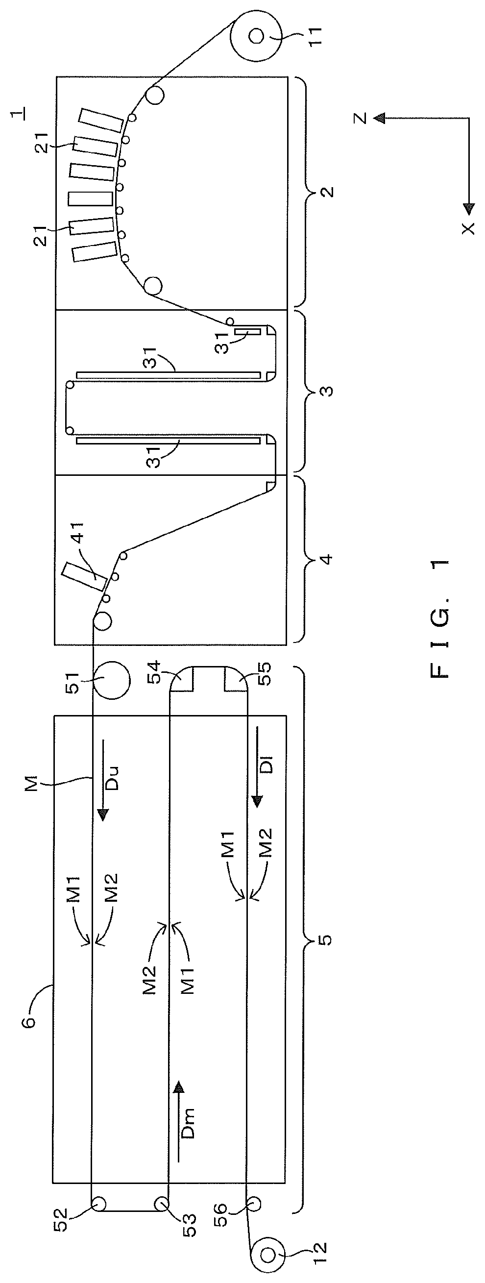
[0017]FIG. 1 is an elevational view schematically showing one example of a printing system including a drying furnace which corresponds to one example of a web drying apparatus in accordance with the present invention. In FIG. 1 and the following figures, a horizontal direction X and a vertical direction Z are shown as appropriate. As shown in FIG. 1, a printing system 1 includes a configuration in which a prestage printer 2, a prestage drying furnace 3, a post-stage printer 4, and a post-stage drying furnace 5 which have the same height are arranged in this order in the horizontal direction X (arrangement direction). This printing system 1 transfers a printing medium M from a feed roll 11 to a wind-up roll 12 in a roll-to-roll process while causing the prestage drying furnace 3 to dry the printing medium M printed by the prestage printer 2 and further causing the post-stage drying furnace 5 to dry the printing medium M printed by the post-stage printer 4. Further, as the printing m...


PUM


Abstract

A web drying apparatus, comprises: a blow-drying part which has two blower units arranged on both sides of web which is transferred in a transfer direction, and injects gas onto the web passing through a dry path between the two blower units; a housing which has a sidewall provided with an opening facing the dry path from the transfer direction, through which the web passes in the transfer direction through the opening, and houses the blow-drying part; an exhaust part which is disposed between the sidewall and the blow-drying part in the housing and exhausts gas from the inside of the housing to the outside of the housing; and a rectifying member which is disposed between the blow-drying part and the exhaust part in the housing and faces the web being transferred in the transfer direction.

Description

CROSS REFERENCE TO RELATED APPLICATION[0001]The disclosure of Japanese Patent Application No. 2019-045605 filed on Mar. 13, 2019 including specification, drawings and claims is incorporated herein by reference in its entirety.BACKGROUND OF THE INVENTION1. Field of the Invention[0002]The present invention relates to a technology for drying web by injecting gas onto the web while transferring the web in a transfer direction.2. Description of the Related Art[0003]Conventionally, a web drying apparatus for drying web by injecting gas onto the web from a blow-drying part has been well known. In a web drying apparatus (drying furnace) disclosed in Japanese Patent Application Laid Open Gazette No. 2000-24574, for example, a blow-drying part provided with two air floating dryers dries web. This web drying apparatus includes the two air floating dryers disposed on both sides (upper and lower sides) of the web being transferred in a transfer direction, and each of the air floating dryers inje...

Claims


Application Information

Patent Timeline
Patent Type & Authority Applications(United States)
IPC IPC(8): F26B13/10F26B21/00
CPCF26B21/004F26B13/108F26B21/001F26B13/10F26B13/28F26B13/06B65H20/10
Inventor UEMURA, RYOTAHIRAI, KEISUKETAKEICHI, YOSHIKUNIMATSUDA, TAKESHIHIRAMATSU, KENTA
Owner DAINIPPON SCREEN MTG CO LTD
Why Eureka
Try Eureka