Pressure pot lock cover structure

A pressure cooker and cover locking technology, applied in the field of pressure cooker, can solve the problems that the air flotation valve will be stuck if there is no virtual position, the cover cannot be rotated, and potential safety hazards, etc. It achieves convenient operation, improved safety, and low cost Effect

Active Publication Date: 2017-02-22
ZHONGSHANCITY GAOTONG ELECTRIC CO LTD
View PDF4 Cites 71 Cited by
  • Summary
  • Abstract
  • Description
  • Claims
  • Application Information

AI Technical Summary

Problems solved by technology

Because there is danger in opening the lid when the air pressure in the pot is high, the existing pressure cookers all have a set of self-locking mechanisms. The lock pin assembly inside the cover, one end of the lock pin assembly is attached to the surface of the pot teeth of the pot body, and the other end of the lock pin assembly extends to the air valve. The float valve will not block the lock pin assembly. When the lid is rotated and opened, the lock pin assembly can move freely along the surface of the pot teeth without affecting the opening of the lid; on the contrary, when the pressure in the pot is too high, the air float valve blocks the lock pin assembly. As a result, the lock pin assembly cannot move freely along the surface of the pot teeth of the pot body, so the pot cover cannot be rotated, so that the cover cannot be opened
Of course, the above is only a theoretical state, but there are still certain potential safety hazards in this structure, because there must be a certain virtual position between the air flotation valve and the lock pin assembly (if there is no vacant position, the air flotation valve will be stuck. dead), even in the case of high pressure in the pot, if the force acting on the rotation and opening of the pot lid is large, the lock pin assembly can overcome the resistance of the air flotation valve and change the state of the air flotation valve, so that Opening the cover in a state that is not conducive to opening the cover will bring huge safety hazards, so it is necessary to improve the structure

Method used


Image

  • Pressure pot lock cover structure
  • Pressure pot lock cover structure
  • Pressure pot lock cover structure

Examples


Embodiment 1

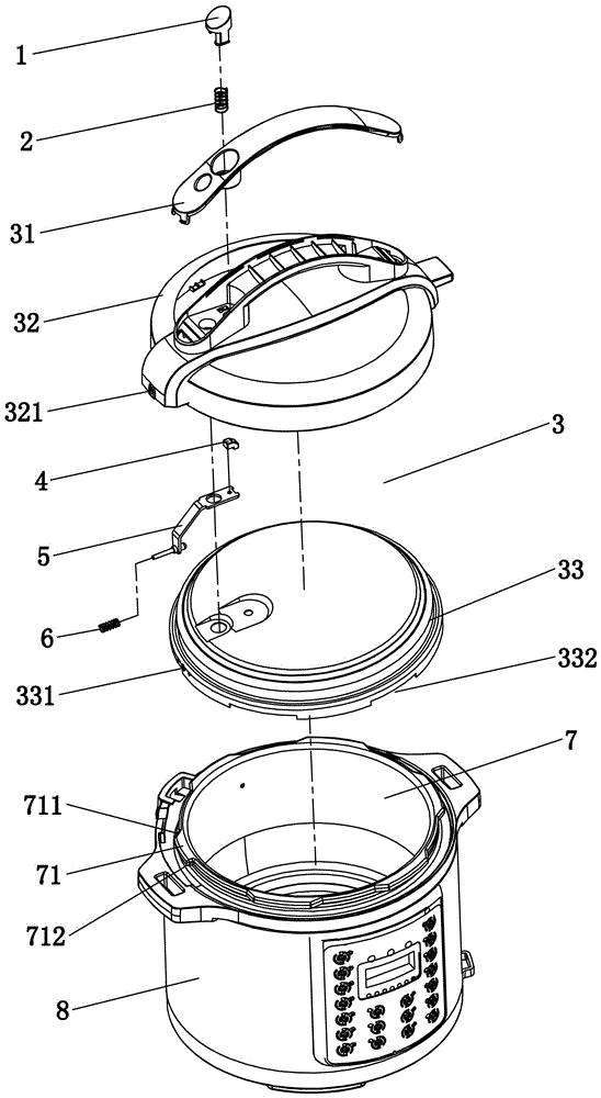
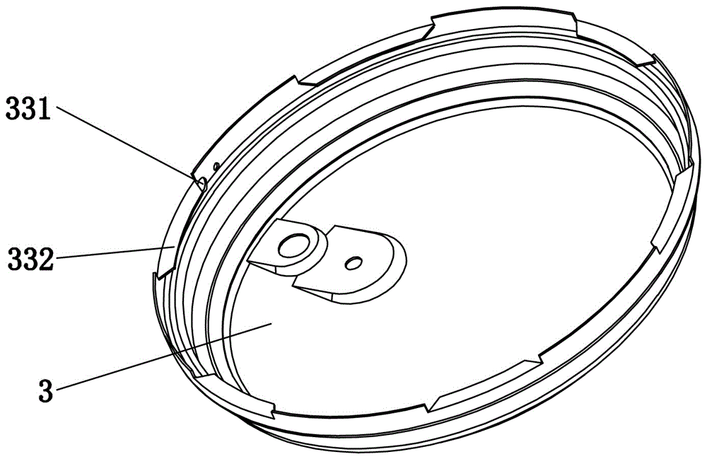
[0030] Embodiment one, see Figure 1 to Figure 6 As shown, a pressure cooker cover structure includes a pot body 8 and a pot cover 3, a plurality of lower pot teeth 71 are annularly arranged on the top of the pot body 8, and upper pot teeth 332 are arranged at the bottom of the pot cover 3, and the upper pot teeth 332 are connected with the lower pot teeth. The number of pot teeth 71 is the same, and the two sides of the lower pot teeth 71 are respectively provided with a forward side 711 and a reverse side, wherein the reverse side of one of the lower pot teeth 71 is a blocking side 712, and the positive side 711 and the rest of the opposite sides are guide hypotenuses; the pot cover 3 is also horizontally slid and provided with a lock pin 52, and the lock pin 52 is located at one end of the upper pot tooth 332 corresponding to the lower pot tooth 71 with the blocking edge 712 above, and the lock pin 52 points to the center of the pot body 8; when the pot cover 3 and the pot ...

Embodiment 2

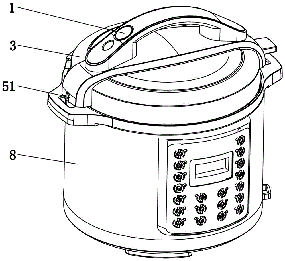
[0040] Embodiment two, the difference with embodiment one is: see Figure 8 Shown, cancel the relevant parts such as button body 1, and directly set handle 9 on the end that locating pin 51 stretches out pot cover 3, when lock pin and blocking side block, by pulling handle 9 outwards, just can Make the lock pin leave the blocking edge, and now the pot cover can be turned. This structure is only different in the way of controlling the reset of the lock pin from that in Embodiment 1, but the principle is the same, and will not be described in detail here.


PUM


Abstract

The invention relates to a pressure pot lock cover structure which comprises a pot body and a pot cover. A plurality of lower pot teeth are annularly arranged on the top of the pot body. Upper pot teeth are arranged at the bottom of the pot cover. The number of the upper pot teeth is the same as that of the lower pot teeth. The two sides of each lower pot tooth are provided with a forward side edge and a reverse side edge respectively, wherein the reverse side edge of at least one lower pot tooth is a blocking edge, and the forward side edges and the other reverse side edges are guiding bevels. A lock pin is transversely arranged inside the pot cover in a sliding mode. The lock pin is located at the portion above the end, corresponding to the lower pot teeth with the blocking edges, of the upper pot teeth. The lock pin points to the center of the pot body. When the pot cover and the pot body are closed, the upper pot teeth are buckled to the bottom of the corresponding lower pot teeth, the lock pin and the blocking edges are blocked, and the outer surface of the pot cover is provided with an unlocking control for controlling the lock pin to get away from the blocking edges. The structure has the advantages that safety and reliability are achieved, the cost is low, operation is convenient, the structure is simple and easy to use, it is ensured that a pressure pot cover cannot be opened violently in the using process of an electric pressure pot, and one-button uncovering can be achieved in a matched mode.

Description

technical field [0001] The invention relates to the technical field of pressure cookers, in particular to a pressure cooker cover locking structure. Background technique [0002] Taking the current electric pressure cooker as an example, it includes a pot body and a pot cover. The top of the pot body is annularly arranged with concavo-convex pot teeth, and the inner wall of the pot cover is provided with buckles corresponding to the pot teeth. Under the pot teeth, the pot lid is buckled with the lid body. On the contrary, when the buckle rotates with the pot cover to the bottom of the recessed pot teeth, the pot lid can be turned up or opened. Because there is danger in opening the lid when the air pressure in the pot is high, the existing pressure cookers all have a set of self-locking mechanisms. The lock pin assembly inside the cover, one end of the lock pin assembly is attached to the surface of the pot teeth of the pot body, and the other end of the lock pin assembly e...

Claims


Application Information

Patent Timeline
Patent Type & Authority Applications(China)
IPC IPC(8): A47J27/08A47J45/06
CPCA47J27/0815A47J45/061
Inventor 王双
Owner ZHONGSHANCITY GAOTONG ELECTRIC CO LTD
Why Eureka
Try Eureka