Cylinder ejecting shaft device

A jacking device and cylinder-type technology, which is applied in transportation and packaging, delivery of filamentous materials, thin material processing, etc., can solve problems such as hidden dangers, loose jacking, and looseness in the winding process

Inactive Publication Date: 2017-02-22
ZHANGJIAGANG TWENTSCHE CABLE
View PDF9 Cites 7 Cited by
  • Summary
  • Abstract
  • Description
  • Claims
  • Application Information

AI Technical Summary

Problems solved by technology

[0002] When the cable factory produces wires, the take-up reel needs to be tightly installed on the equipment. In the existing structure, force is manually applied to the top center to make the top center tighten the take-up fiber reel. The top center stroke of the top center is fixed. After the core is in place, fix the top center. Since the top center is fixed, it cannot be adjusted, so there is a risk that the top is not tight or loose, which makes the winding process a hidden danger.

Method used


Image

  • Cylinder ejecting shaft device

Examples


Embodiment Construction

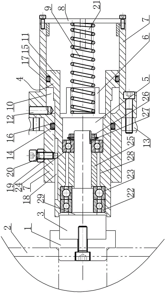
[0013] A cylinder type jacking device, see figure 1 : It includes a top core 1, the top core end surface of the top core 1 is arranged towards the take-up fiber reel 2, one end of the top core 1 away from the top core end surface is fastened to one end of the top core shaft 3, and the other end of the top core shaft 3 passes through The bearing is installed in the front central installation cavity 5 of the movable cylinder 4, the central rear end of the movable cylinder 4 is fixedly equipped with a spring seat 6, and the cylinder seat 7 is set on the outer ring surface of the rear end of the movable cylinder 4, and the rear end of the cylinder seat 7 The cover is equipped with a back cover 8, the back cover 8 is located at the rear of the spring seat 6, the spring seat 6 and the back cover 8 are plugged with a compressed linear spring 9, and the cylinder seat 7 is set on the rear end outer ring surface of the movable cylinder 4 and then they contact each other A closed annular...


PUM


Abstract

The invention provides a cylinder ejecting shaft device for acting on an ejecting center through a spring effect to guarantee ejection without generating the loosening risk and pneumatically recovering the ejecting center to guarantee quick and convenient whole loosening process. The cylinder ejecting shaft device comprises the ejecting center; and the ejecting center end surface of the ejecting center is arranged towards a wire collecting disc. The cylinder ejecting shaft device is characterized in that one end, far from the ejecting center end surface, of the ejecting center is tightly connected to one end of an ejecting center shaft; the other end of the ejecting center shaft is mounted in a mounting cavity in the center of the front part of a movable cylinder through a bearing; a spring base is fixedly mounted at the back end of the center of the movable cylinder; a cylinder base coats the outer ring surface of the back end of the movable cylinder; a back cover covers the back end of the cylinder base, and is positioned behind the spring base; the spring base and the back cover are plugged with compression linear springs; after the cylinder base coats the outer ring surface of the back end of the movable cylinder, an annular axial gap with one closed end is formed between the ring walls thereof contacted with each other; and the back end of the annular axial gap is a back end ring part of the movable cylinder.

Description

technical field [0001] The invention relates to the technical field of silicone oil brushing, in particular to a cylinder type jacking device. Background technique [0002] When the cable factory produces wires, the take-up reel needs to be tightly installed on the equipment. In the existing structure, force is manually applied to the top center to make the top center tighten the wire fiber reel. The top center stroke of the top center is fixed, and the top center After the center is in place, the top center is fixed. Since the top center is fixed, it cannot be adjusted, so there is a risk that the top is not tight or loose, which makes the winding process a hidden danger. Contents of the invention [0003] Aiming at the above problems, the present invention provides a cylinder-type jacking device, which acts on the center of the shaft through a spring to ensure tightness without risk of loosening, and retracts the center of the shaft pneumatically to ensure that the whole...

Claims


Application Information

Patent Timeline
Patent Type & Authority Applications(China)
IPC IPC(8): B65H54/54
CPCB65H54/54
Inventor 陆晓伟杨政国季春华李保东葛小卫
Owner ZHANGJIAGANG TWENTSCHE CABLE
Why Eureka
Try Eureka