
Mechanical sealing device for slurry pump

A mechanical seal device and slurry pump technology, which is applied to mechanical equipment, parts of pumping devices for elastic fluids, pumps, etc., can solve the problems of short service life and easy damage, achieve long service life, reduce direct damage, etc. Impact and cost-saving effect

Inactive Publication Date: 2017-02-22
天津市富鑫达密封有限公司
View PDF9 Cites 0 Cited by
  • Summary
  • Abstract
  • Description
  • Claims
  • Application Information

AI Technical Summary

Problems solved by technology

Traditional mechanical seals for pumps cannot meet the high requirements of long service life in the application of desulfurization equipment in electric power, industrial and mining enterprises, etc. A mechanical seal device for slurry pumps breaks the shortcomings of traditional mechanical seals for desulfurization pumps, Through the structural design of the O-shaped rubber sealing ring on the transmission pin of the moving ring part and the static ring part, the direct impact on the moving ring part and the static ring part when the transmission pin rotates is reduced, and the moving ring part and the static ring part are not impacted by the transmission pin. And broken, it solves the problem of easy damage and short service life of the mechanical seal of the traditional desulfurization pump, improves the production efficiency, saves the cost, ensures the safety of the product, and provides a facility guarantee for the production and development of electric power, industrial and mining enterprises.

Method used


Image

  • Mechanical sealing device for slurry pump
  • Mechanical sealing device for slurry pump
  • Mechanical sealing device for slurry pump

Examples


Embodiment Construction

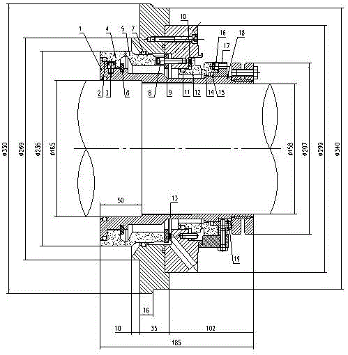
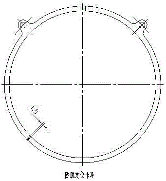
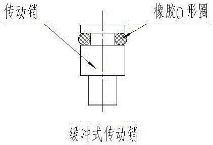
[0012] The specific implementation manner of the present invention will be described in detail below in conjunction with the accompanying drawings and preferred embodiments. Its structural diagram is as shown in the accompanying drawings. A mechanical seal device for a slurry pump, comprising an inner seal and an outer seal. The inner seal includes an inner moving ring 4, an inner static ring 5, O-rings 2 and 7, a buffer transmission pin 3, a shaft circlip 6, a spring push ring 9 and a spring 13, which are used for sealing liquid and medium of the seal. The outer seal includes an outer moving ring 14, an outer stationary ring 12, O-rings 11 and 15, a buffer transmission pin 16, a push ring 17, a spring 10 and an anti-off positioning snap ring 18 for sealing the sealing liquid. The shaft sleeve 1 is locked on the shaft, the inner moving ring 4 and the outer moving ring 14 rotate simultaneously with the shaft sleeve 1 driven by the shaft, the buffer transmission pin 3 drives t...


PUM


Abstract

The invention belongs to the field of mechanical sealing and particularly relates to a mechanical sealing device for a slurry pump. The mechanical sealing device for the slurry pump comprises an internal seal and an external seal. The mechanical sealing device is characterized in that the internal seal comprises an internal movable ring, an internal fixed ring, an O-shaped ring, a cushioning type drive pin, an elastic shaft retaining ring, a spring push ring and a spring and used for sealing of sealing liquid and a medium; the external seal comprises an external movable ring, an external fixed ring, an O-shaped ring, a cushioning type drive pin, a push ring, a spring and an anti-disengaging positioning clamping ring and used for sealing of sealing liquid; and the internal movable ring and the internal fixed ring are used for sealing the medium, the outer movable ring and the outer fixed ring are used for sealing the liquid, and clean sealing face lubricating and heat dissipation are provided. The mechanical sealing device for the slurry pump has the beneficial effects of being perfect in performance, low in cost, safe and reliable, long in service life and easy to damage. By the adoption of the mechanical sealing device for the slurry pump, the problems that a traditional mechanical seal for a desulfurization pump is easy to damage and short in service life can be completely solved. It is proved by the practice that the device can be used for production and scientific experiments in the industries of power, industrial and mining enterprises and the like, and the device is completely feasible in terms of technology, economy and environmental protection.

Description

technical field [0001] The invention belongs to the field of mechanical seals, in particular to a mechanical seal device for a slurry pump. Background technique [0002] Mechanical seal technology is widely used in national defense, electric power, chemical industry, petroleum, metallurgy, transportation, medicine, food, cosmetics and other fields. The application of a mechanical seal device for a slurry pump is an important aspect in the field of mechanical seals. The utility model belongs to a mechanical seal for a pump. Traditional mechanical seals for pumps cannot meet the high requirements of long service life in the application of desulfurization equipment in electric power, industrial and mining enterprises, etc. A mechanical seal device for slurry pumps breaks the shortcomings of traditional mechanical seals for desulfurization pumps, Through the structural design of the O-shaped rubber sealing ring on the transmission pin of the moving ring part and the static ring...

Claims


Application Information

Patent Timeline
IPC IPC(8): F04D29/08
Inventor 任伟李玲张福华
Owner 天津市富鑫达密封有限公司
Features
  • Generate Ideas
  • Intellectual Property
  • Life Sciences
  • Materials
  • Tech Scout
  • Unparalleled Data Quality
  • Higher Quality Content
  • 60% Fewer Hallucinations
Learn More