
Spool outer ring spiral groove type 2d electro-hydraulic high-speed switch valve

A high-speed switching valve, spiral groove technology, applied in multi-way valve, valve device, valve details and other directions, can solve the problem of weak and strong spool machining precision spool and other problems, achieve high self-cleaning ability, increase control flow, increase Effect of Spool Diameter

Active Publication Date: 2018-11-13
ZHEJIANG UNIV OF TECH
View PDF7 Cites 0 Cited by
  • Summary
  • Abstract
  • Description
  • Claims
  • Application Information

AI Technical Summary

Problems solved by technology

[0006] In order to overcome the existing 2D electro-hydraulic high-speed switching valves that are prone to friction, hydraulic power, oil pollution, weak and strong valve cores, and machining accuracy problems, the hydraulic "stuck" phenomenon on the valve core, and to increase the servo spiral groove and high and low pressure The area gradient of the groove intersecting improves the frequency response. The invention provides a 2D electro-hydraulic high-speed switching valve with a spiral groove on the outer ring of the valve core that can realize the rapid response of the servo screw mechanism and strong anti-pollution ability under high pressure and large flow.

Method used


Image

  • Spool outer ring spiral groove type 2d electro-hydraulic high-speed switch valve
  • Spool outer ring spiral groove type 2d electro-hydraulic high-speed switch valve
  • Spool outer ring spiral groove type 2d electro-hydraulic high-speed switch valve

Examples


Embodiment Construction

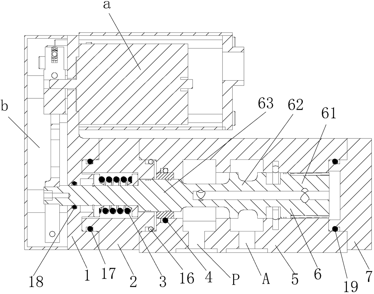
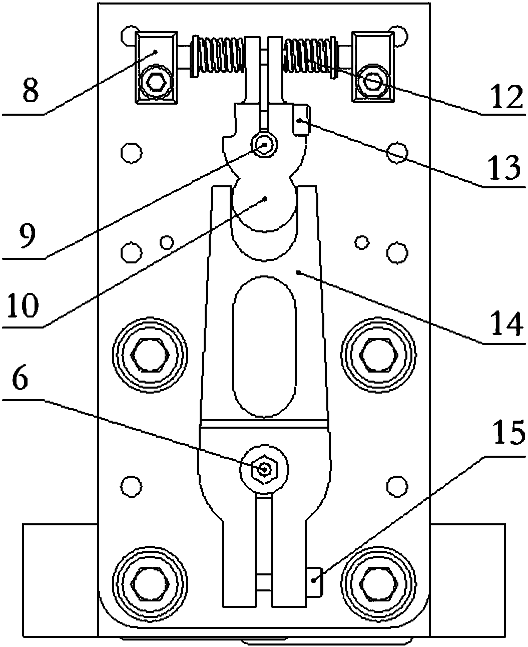
[0042] As shown in the figure, the spiral groove type 2D electro-hydraulic high-speed switch valve on the outer ring of the valve core includes the valve body, the transmission mechanism that drives the valve body to open or close, and the zero position holding mechanism that drives the valve body to reset;

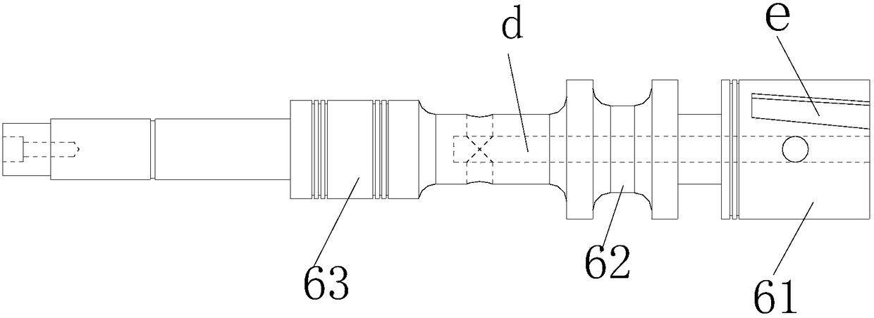
[0043] The valve body includes a servo screw mechanism composed of a valve body 5 and a valve core 6. The valve core 6 is rotatably arranged in the valve body 5. The valve core 6 is provided with a first shoulder 61 and a second shoulder in sequence from right to left. 62 and the third shoulder 63, the right end cover 7 and the first shoulder 61 of the valve body 5 airtightly enclose the inner cavity of the valve body 5 into a sensitive chamber i, and the first shoulder 61 and the second shoulder 62 seal the valve body 5. The inner cavity of the valve body 5 is airtightly enclosed to form an annular oil outlet cavity surrounding the spool 6, and the second shoulder 62 and ...


PUM


Abstract

The invention discloses a two-dimensional electro-hydraulic high-speed switch valve with the outer ring of a valve element provided with spiral grooves. The two-dimensional electro-hydraulic high-speed switch valve comprises a valve body, a drive mechanism used for driving the valve body to be opened or closed, and a null position holding mechanism used for driving the valve body to restore in position. The valve body comprises a servo spiral mechanism composed of a valve body part and the valve element. An oil inlet cavity communicates with an oil inlet in the valve body part. The inlet end of a high-pressure channel communicates with the oil inlet cavity. The inlet end of a low-pressure channel communicates with low-pressure grooves. The outlet end of the low-pressure channel communicates with an oil outlet cavity. One ends of the spiral grooves communicate with a sensitive cavity, and the other ends of the spiral grooves are located on motion tracks of the high-pressure grooves and motion tracks of the low-pressure grooves. A rotary shaft of a rotary device is fixedly connected with an upper shifting rod. An upper shifting rod reset spring is used for enabling the upper shifting rod to vertically abut against the inside of a lower shifting fork. The left end of the valve element penetrates through the valve body part; and the null position holding mechanism used for keeping the vale body at the null position is arranged on the left side of the valve body.

Description

technical field [0001] The invention relates to an on-off valve, in particular to a 2D electro-hydraulic high-speed on-off valve with a spiral groove on the outer ring of a valve core. Background technique [0002] High-speed switching valve is an electro-hydraulic control element developed in the 1980s. It has the advantages of fast switching ability and strong anti-pollution ability. It is widely used in hydraulic locking, aerospace, construction machinery and military fields. [0003] In recent years, as one of the key components of electro-hydraulic digital control technology, the high-speed on-off valve has higher and higher performance requirements in order to realize the organic combination of computer technology and hydraulic control technology. It meets the characteristics of large flow, high pressure resistance, fast response, high control precision and good sealing performance. [0004] As the control element of the hydraulic system, the structure of the valve bo...

Claims


Application Information

Patent Timeline
Patent Type & Authority Patents(China)
IPC IPC(8): F16K11/065F16B13/02F16K27/04F16K31/04
CPCF16B13/02F16K11/065F16K27/04F16K31/04
Inventor 贾文昂吴圣裴翔赵志鹏申屠胜男
Owner ZHEJIANG UNIV OF TECH
Learn More