LED ceiling lamp

A technology for LED ceiling lamps and LED light panels, which is applied to lighting and heating equipment, semiconductor devices of light-emitting elements, lighting devices, etc. The effect of improving safety

Active Publication Date: 2017-02-22
NINGBO QICHI ILLUMINATION LAMP
View PDF8 Cites 6 Cited by
  • Summary
  • Abstract
  • Description
  • Claims
  • Application Information

AI Technical Summary

Problems solved by technology

Since it is divided into two parts, there needs to be a wire to connect the front part and the rear part. If this wire is installed with the rear part, it will be hung together with the front part, which will affect the installation. When buckled together, the wire will be twisted randomly to hinder the buckle or other positioning structures, resulting in unsmooth installation. It needs to be repeated several times or more to get the correct alignment.

Method used


Image

  • LED ceiling lamp
  • LED ceiling lamp
  • LED ceiling lamp

Examples


Embodiment 1

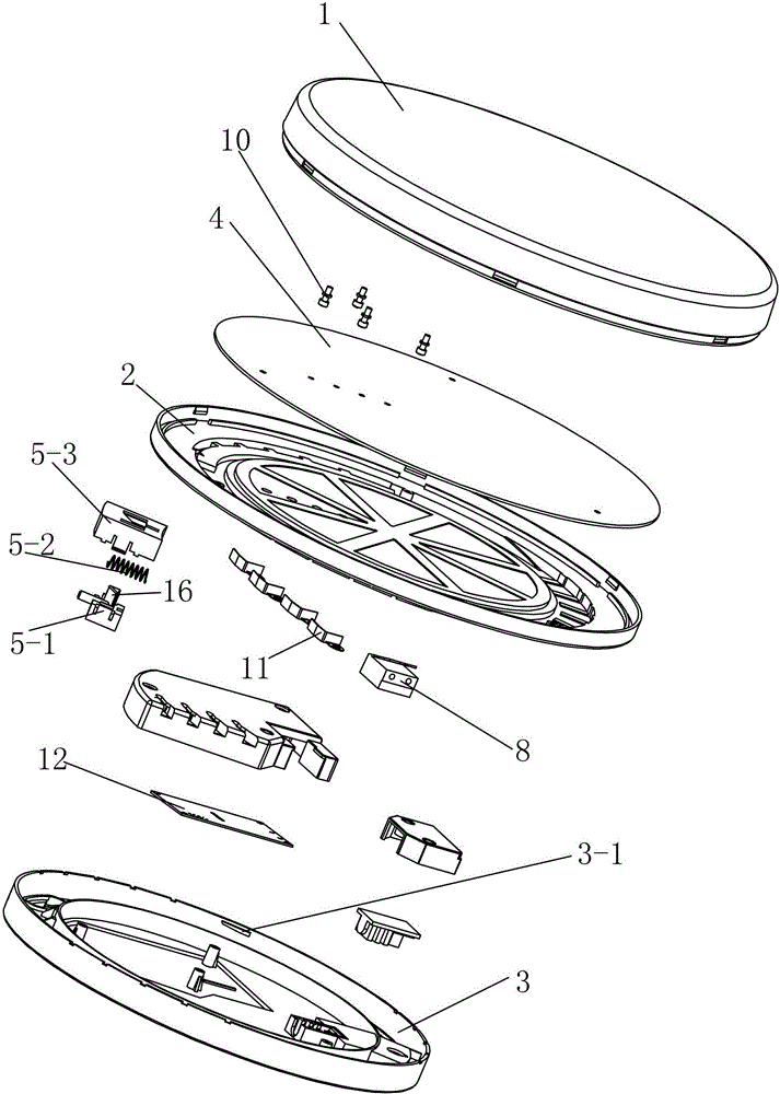
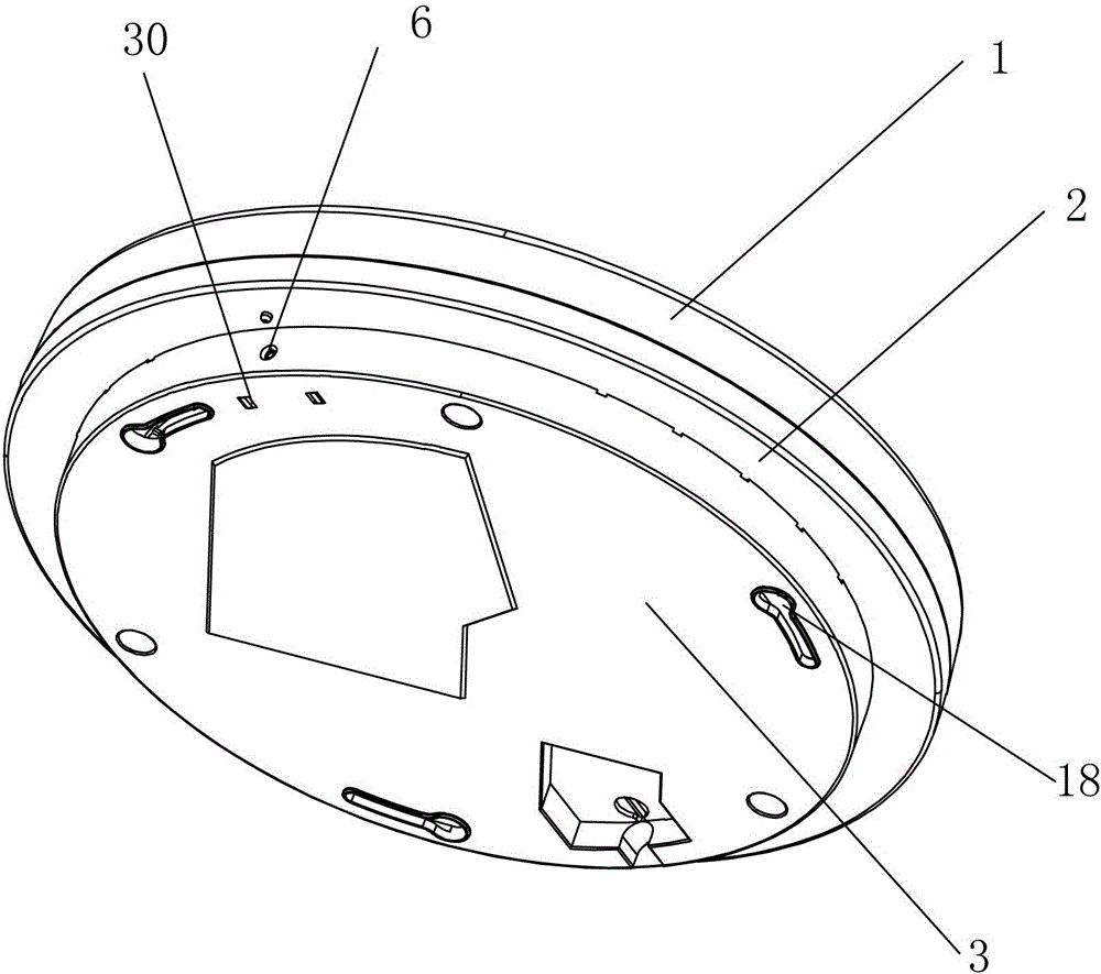
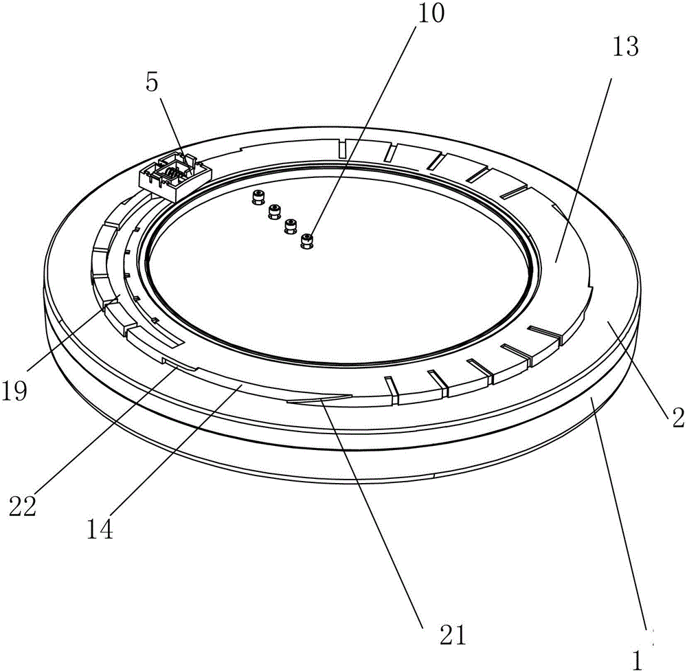
[0029] Such as Figure 1 to Figure 6As shown, the LED ceiling lamp provided in this embodiment includes a lampshade 1, a base 2, a fixing seat 3, a locking device 5, more than one metal terminal 10, more than one metal sheet 11, an LED lamp board 4, a control The circuit board 12 and the connecting terminal 8 are provided with a first mounting hole 18 on the fixing seat 3, and the LED lamp board 4 is provided in the upper end surface of the base 2, and the lower end surface of the base 2 is provided with an annular boss 13 First grooves 14 are evenly distributed on the annular side wall of the annular boss 13, and the fixed base 3 is provided with a groove that can circle the first groove 14 in the first groove 14 when the base 2 and the fixed base 3 are rotated and installed. The wedge block 3-1 for limit locking after the groove 14 moves circularly. The locking device 5 includes a locking block 5-1, a spring 5-2 and a locking block cover 5-3. The locking block 5-1 One end r...

Embodiment 2

[0034] Such as Figure 7 , Figure 8 As shown, the general structure of the LED ceiling lamp provided by this embodiment is the same as that of Embodiment 1. The difference is to prevent internal water from entering and improve the drainage effect. The inside of the annular boss 13 is provided with an inner groove 23. A second groove 24 and a sealing ring 25 located in the second groove 24 are annularly provided at the junction of the platform 13 and the inner groove 23, and an annular baffle 26 cooperating with the sealing ring 25 is provided in the fixed seat 3, and the ring Outlet grooves 27 are uniformly distributed on the upper circumference of the boss 13, the outlet grooves 27 are connected with the outer periphery of the annular boss 13, and a concave hole 28 cooperating with the water outlet groove 27 is formed on the fixing seat 3, and the concave hole 28 and the The corresponding water outlet grooves 27 cooperate with each other to make the fixed seat 3 and the bas...

Embodiment 3

[0036] Such as Figure 9 , Figure 10 , Figure 11 As shown, the general structure of the LED ceiling lamp provided by this embodiment is the same as that of Embodiment 2. The difference is that in order to improve safety, one end of each metal sheet 11 is respectively fixed on the power cover 31 by screws and connected to the control circuit board 12. Electrically connected, the other end of each metal sheet 11 is in one-to-one contact with the metal terminal 10 protruding into the power supply cover 31 during installation, the control circuit board 12 is fixed in the power supply cover 31, and the power supply cover 31 is fixed In the fixed seat 3, one side of the power supply cover 31 is provided with a connecting terminal 8 electrically connected to the control circuit board 12, and in the fixed seat 3, a waterproof silica gel block 9 for wearing external electric wires is also provided. In the waterproof silica gel block 9 There is a cover 7 on it. After the installatio...


PUM


Abstract

The invention discloses an LED ceiling lamp which comprises a lampshade, a base, a fixing base, a locking device, metal terminals, metal sheets, an LED lamp panel arranged in a cavity of the base, a power source cover arranged on the end face of the base, a cover body and a wiring terminal. The lampshade and the base are buckled to each other. A waterproof silica gel block is fixed in the cover body. An LED control driver is installed in the power source cover. The hollow portion of the fixing base is provided with wedge blocks and mounting holes. Mounting grooves in one-to-one correspondence with the wedge blocks are formed in the end face of the base. The locking device is further fixed to the end face of the base. The locking device comprises a locking block, a spring and a locking block cover. The locking block is clamped in the locking block cover through the spring. The mounting holes and the locking block are matched in a fixed mode. The metal sheets are installed in the power source cover. The LED lamp panel is pivoted to the metal sheets through the metal terminals. The LED ceiling lamp has the characteristics of being convenient to mount and dis mount and good in firmness.

Description

technical field [0001] The invention relates to the technical field of LED lamps, in particular to LED ceiling lamps. Background technique [0002] At present, most of the components of the LED ceiling lamps on the market are installed through brackets, which will make installation and disassembly inconvenient, and the firmness between the components of the LED ceiling lamps is not enough, which will cause the ceiling lamps to loosen and have a short service life. [0003] At present, most of the LED ceiling lamps on the market have built-in drivers, and the built-in drivers are generally divided into two types: isolation schemes and non-isolation schemes. Although the isolation scheme is safe, it has high cost, low work conversion efficiency, low cost performance, and no competitive advantage. The non-isolated solution has low cost, high conversion efficiency, and high cost performance. As long as the parts that can be touched by the human body are well insulated, it can m...

Claims


Application Information

Patent Timeline
IPC IPC(8): F21S8/04F21V17/16F21V23/06F21Y115/10
CPCF21S8/04F21V17/162F21V17/164F21V23/06
Inventor 金光威邹忠惠
Owner NINGBO QICHI ILLUMINATION LAMP
Why Eureka
Try Eureka