
Boiler expansion monitoring system and monitoring method

A technology for monitoring systems and boilers, applied to measuring devices, instruments, optical devices, etc., can solve the problems of low measurement accuracy, time-consuming and labor-intensive, short-term failure, etc.

Pending Publication Date: 2017-02-22
BEIJING YUANSHEN ENERGY SAVING TECH
View PDF0 Cites 9 Cited by
  • Summary
  • Abstract
  • Description
  • Claims
  • Application Information

AI Technical Summary

Problems solved by technology

When the expansion encounters resistance or the guide device fails, the actual expansion and the design value will deviate, and the stress of the relevant stress-bearing components will change greatly, and the metal life will be greatly reduced, or even short-term failure.
[0003] Now most of the boiler body is designed with a set of mechanical monitoring device. This device has simple structure, low measurement accuracy, and large data deviation, resulting in inaccurate measurement of the expansion of the boiler body, which leads to hidden dangers in the safe operation of the boiler, and requires manual climbing to the installation point. Reading parameters is time-consuming and labor-intensive
Due to the large number of test points and the distance between them, if the expansion speed of the boiler is fast, it is impossible to monitor and read the change of expansion displacement at the first time, resulting in the omission of parameter information

Method used


Image

  • Boiler expansion monitoring system and monitoring method
  • Boiler expansion monitoring system and monitoring method
  • Boiler expansion monitoring system and monitoring method

Examples


Embodiment Construction

[0026] Embodiments of the present invention are described in detail below, examples of which are shown in the drawings, wherein the same or similar reference numerals designate the same or similar elements or elements having the same or similar functions throughout. The embodiments described below by referring to the figures are exemplary only for explaining the present invention and should not be construed as limiting the present invention.

[0027] In describing the present invention, it should be understood that the terms "center", "longitudinal", "transverse", "upper", "lower", "front", "rear", "left", "right", " The orientations or positional relationships indicated by "vertical", "horizontal", "top", "bottom", "inner" and "outer" are based on the orientations or positional relationships shown in the drawings, and are only for the convenience of describing the present invention and Simplified descriptions, rather than indicating or implying that the device or element refe...


PUM


Abstract

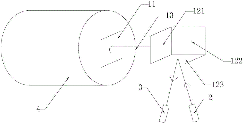
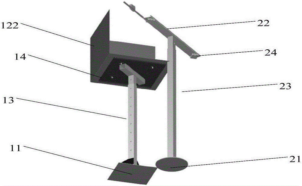
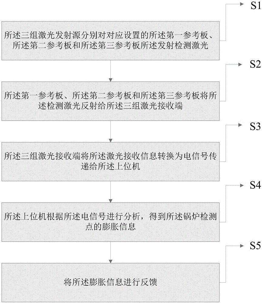
The invention discloses a boiler expansion monitoring system and a monitoring method. The boiler expansion monitoring system comprises a reference monitoring device, a laser emission device, a laser receiving device, and an upper computer. The reference monitoring device comprises three reference plates, which are vertical to each other, and are used to form a three-dimensional coordinate. The laser emission device comprises three laser emission sources, which are used to emit monitoring laser. The laser receiving device comprises three laser receiving ends, which are used to receive the reflected laser. The upper computer is used for analysis and feedback according to laser receiving information transmitted by three laser receiving ends. The boiler expansion monitoring system and the monitoring method are advantageous in that a boiler monitoring point is fixedly connected with a reference monitoring device, and the laser monitoring is carried out by the three reference plates, which are disposed on the reference monitoring device, are vertical to each other, and are used to form the three-dimensional coordinate; after the boiler monitoring point is expanded, the three reference plates on the reference monitoring device is deviated, and then the reflected laser received by the laser receiving device is deviated, and by calculating deviation amounts, the expansion information of the boiler monitoring point is acquired.

Description

technical field [0001] The invention relates to the field of boiler expansion monitoring, in particular to a boiler expansion monitoring system and a monitoring method. Background technique [0002] Most of the large-scale power plant boilers adopt a fully suspended structure, so that each part of the boiler body can have relatively sufficient thermal expansion, which greatly reduces the thermal stress caused by the hindered thermal expansion. In order to calculate the thermal expansion displacement more accurately, so as to carry out the stress analysis and seal design of the system, it is necessary to have an expansion center that remains unchanged under various working conditions. By setting the boiler expansion center and the boiler guide device (some structures on the rigid beam and steel frame), it is hoped that the expansion center will be used as the starting point and the expansion will be carried out in a predetermined direction. When the expansion encounters resi...

Claims


Application Information

Patent Timeline
IPC IPC(8): G01B11/02
Inventor 王彦龙李前宇李振华徐义巍赵岩杨伴龙赵民政谢正和
Owner BEIJING YUANSHEN ENERGY SAVING TECH
Learn More