Riser removing hammer test device

A test device and a technology for removing risers, which are applied in the field of foundry machinery and can solve the problems of increasing the diameter of the bottom of the lead column, etc.

Inactive Publication Date: 2017-02-22
JINAN CASTING FORGING MACHINERY INST
View PDF9 Cites 0 Cited by
  • Summary
  • Abstract
  • Description
  • Claims
  • Application Information

AI Technical Summary

Problems solved by technology

Previously, a cylinder whose inner diameter was the same as the diameter of the lead column sample and whose height was one third of the diameter of the lead column sample was fixed on the vertical plate, and the lead column sample was directly placed in the cylinder, which solved the problem of the lead column. The problem is that the sample is placed horizontally, but after hitting the lead column sample, the diameter of the bottom of the lead column will become larger, and the existence of the cylinder will limit the expansion of the bottom of the lead column, which will result in the authenticity of the height of the lead column after one hit

Method used


Image

  • Riser removing hammer test device
  • Riser removing hammer test device
  • Riser removing hammer test device

Examples


Embodiment Construction

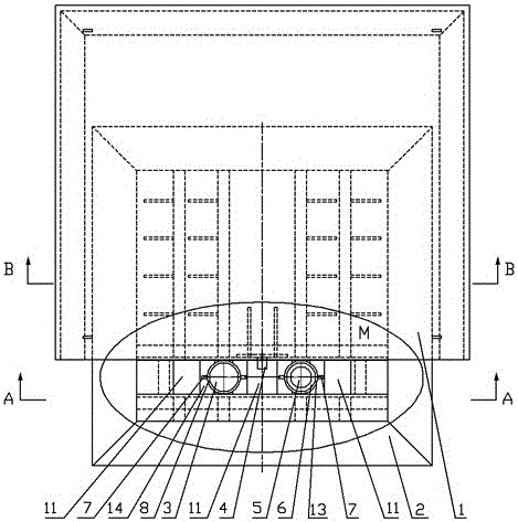
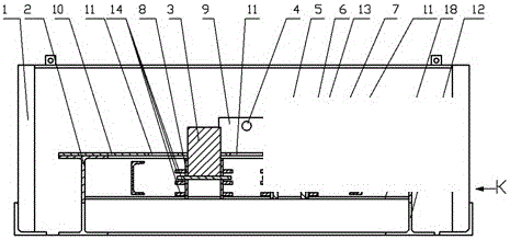
[0023] Such as figure 2 Shown, a kind of riser hammer test device, it comprises base 2, and base 2 is made up of several beams 19 and longitudinal beam 17 welded together, also comprises two sample sleeves welded on the beam 19, sample cover There are three pairs of clamping plates 14 arranged horizontally on the outer side of the tube from top to bottom to weld the sample sleeve and beam 19 together. The clamping plates 14 are provided with arc-shaped grooves that match the shape of the outer wall of the sample sleeve; the sample sleeve The upper plane of the cylinder is flush with the upper plane of the base 2, and the sample sleeve includes a fatigue sample sleeve 8 and a failure sample sleeve 13, and an adjustment sleeve 6 is placed in the failure sample sleeve 13, and the outer diameter of the adjustment sleeve 6 is the same as the failure specimen sleeve 13. The inner diameter of the sample sleeve 13 is the same, the inner diameter of the adjusting sleeve 6 is consistent...


PUM


Abstract

The invention relates to a riser removing hammer test device. The riser removing hammer test device comprises a base. A plurality of cross beams and longitudinal beams are welded together to form the base. The riser removing hammer test device is characterized in that the riser removing hammer test device further comprises two sample sleeves welded to the cross beams of the base; the sample sleeves and the cross beams are welded together through three pairs of horizontally-arranged clamping boards which are distributed at the outer sides of the sample sleeves from top to bottom; the clamping boards are provided with arc-shaped grooves which are shaped to match the outer walls of the sample sleeves; the upper planes of the sample sleeves are flush with the upper plane of the base; an adjustment sheath is arranged in one of the sample sleeves; the outer diameter of the adjustment sheath is consistent with the inner diameter of the sample sleeve; the inner diameter of the adjustment sheath is consistent with the diameter of a destroying sample; and pin holes are formed in the sample sleeves and the adjustment sheath respectively.

Description

technical field [0001] The application belongs to the field of foundry machinery, and relates to a test device for riser removal equipment in the post-treatment process of castings. Background technique [0002] In the casting production process of the foundry industry, especially the production of large castings, the removal of the sprue and riser has always been a difficult problem. Traditionally, gas cutting, manual hammering with a sledgehammer, or the use of a crane to hoist a metal weight to hit the riser will cause problems such as energy consumption, casting quality damage, low efficiency, and unsafety. In order to solve this difficult problem, a kind of riser removal hammer is adopted to remove the riser now. Align the casing of the de-riser hammer with the riser, press the button valve, the piston rod will rush out from the casing, and break the riser with enough energy. Before selling the riser hammer, the size of the impact energy, the diameter of the riser of ...

Claims


Application Information

Patent Timeline
Patent Type & Authority Applications(China)
IPC IPC(8): G01M13/00G01N3/34
CPCG01M13/00G01N3/34
Inventor 姚继成包艳青
Owner JINAN CASTING FORGING MACHINERY INST
Why Eureka
Try Eureka