Gravity sensing data correction method and system

A technology of gravity sensing and data correction, applied in the direction of electrical digital data processing, input/output process of data processing, instruments, etc., can solve problems affecting the use of applications, insensitivity, and opposite movement directions, etc., to improve experience and ensure The effect of normal use

Inactive Publication Date: 2017-02-22
YULONG COMPUTER TELECOMM SCI (SHENZHEN) CO LTD
View PDF3 Cites 4 Cited by
  • Summary
  • Abstract
  • Description
  • Claims
  • Application Information

AI Technical Summary

Problems solved by technology

When the user uses an application program on the second screen, and the normal use of the application program requires gravity sensing data, when the application program is displayed on the second screen for the user to use, the acquired gravity sensing data is not a

Method used


Image

  • Gravity sensing data correction method and system
  • Gravity sensing data correction method and system
  • Gravity sensing data correction method and system

Examples


Example Embodiment

[0097] Embodiment three:

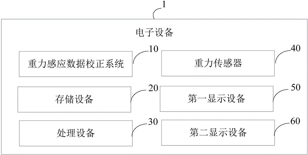
[0098] The acquiring module 100 is configured to acquire gravity sensing data of the gravity sensor 40 of the electronic device 1 .

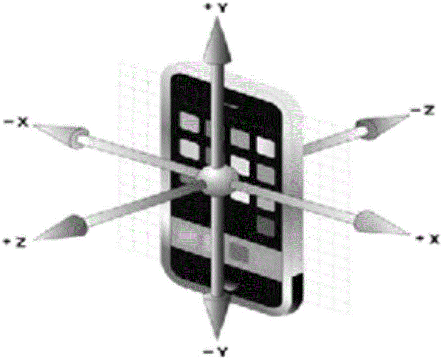
[0099] In this embodiment, when the electronic device 1 is moved, the acquiring module 100 uses the gravity sensor 40 to acquire the gravity sensing data. The gravity sensing data is a vector (a, b, c), including three dimensions, a is a component on the X axis, b is a component on the Y axis, and c is a component on the Z axis.

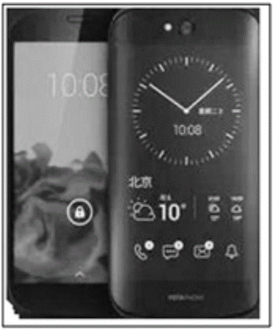
[0100] The determination module 101 is configured to determine the screen display mode of the second display device 60 when the second display device 60 is in use by the gravity sensing data correction system 10 .

[0101] In this embodiment, the screen display modes include horizontal screen and vertical screen. The determination module 101 utilizes the gravity sensor 40 to determine the screen display mode of the second display device 60 . When the determination module 101 uses the gravi...

Example Embodiment

[0112] Embodiment four:

[0113] The acquiring module 100 is configured to acquire gravity sensing data of the gravity sensor 40 of the electronic device 1 .

[0114] In this embodiment, when the electronic device 1 is moved, the acquiring module 100 uses the gravity sensor 40 to acquire the gravity sensing data. The gravity sensing data is a vector (a, b, c), including three dimensions, a is a component on the X axis, b is a component on the Y axis, and c is a component on the Z axis.

[0115] A judging module 103, configured to judge whether the screen display mode of the second display device 60 is a horizontal screen.

[0116] In this embodiment, the screen display modes include horizontal screen and vertical screen. The judging module 103 uses the gravity sensor 40 to determine the screen display mode of the second display device 60 . When the judging module 103 uses the gravity sensor 40 to detect that the current parameter (such as the acceleration vector) of the ele...


PUM


Abstract

The invention discloses a gravity sensing data correction method. The method is applied to electronic equipment, and the electronic equipment comprises first display equipment and second display equipment, wherein the first display equipment is located at the front of the electronic equipment and the second display equipment is located at the back of the electronic equipment. The method comprises the following steps of: obtaining gravity sensing data of a gravity sensor of the electronic equipment, wherein a gravity coordinate system of the gravity sensor is established by taking the first display equipment as a benchmark; when the second display equipment is located in a using state, determining a screen display manner of the second display equipment; and correcting the gravity sensing data according to the screen display manner of the second display equipment. The invention furthermore provides a gravity sensing data correction system. According to the method and system provided by the invention, the gravity sensing data can be corrected timely, so that the normal use of application programs of the electronic equipment is ensured and then the user experience is improved.

Description

technical field [0001] The present invention relates to the field of terminal technology, in particular to a method and system for correcting gravity sensing data. Background technique [0002] Electronic devices usually provide hardware-based sensors and software-based sensors to detect actions of the electronic devices. For example, hardware sensors include a magnetic sensor, an acceleration sensor (accelerometer), and a gyroscope sensor (gyroscope). Based on these two hardware sensors, software sensors can be implemented, such as gravity sensors, linear acceleration sensors, and rotation vector accelerators. The function of the software sensor is realized based on the hardware sensor. [0003] For example, usually the gravity sensor of an electronic device is a software sensor, which has been perfected on a single-screen electronic device (such as a smart phone). For electronic devices with dual screens, the first screen is on the front of the electronic device, and th...

Claims


Application Information

Patent Timeline
IPC IPC(8): G06F3/00
CPCG06F3/002
Inventor 朱洪达赵宏田张学林
Owner YULONG COMPUTER TELECOMM SCI (SHENZHEN) CO LTD
Why Eureka
Try Eureka