Drawer holder for switchgear

A technology for switching electrical appliances and drawer seats, which is applied in the direction of switchgear, pull-out switch cabinets, switchgear parts, etc., and can solve the problem of unclear pull-out state of drawer seats, low transmission efficiency, and inconvenient maintenance and inspection, etc. question

Inactive Publication Date: 2017-02-22
INST OF DONGGUAN TONGJI UNIV
View PDF6 Cites 3 Cited by
  • Summary
  • Abstract
  • Description
  • Claims
  • Application Information

AI Technical Summary

Problems solved by technology

[0004] In the existing drawer seat for switching appliances, since the guide plate has no locking mechanism in the pulled-out position, the pull-out state of the drawer seat is unclear; secondly, the guide plate does not have a locking mechanism in the separated position, and the drawer seat is not very safe in the separated position. Reliable, which threatens the safety of switching electrical appliances; again, there is no locking mechanism between the two guide plates. When the drawer seat is pulled out, the body on the drawer seat cannot be completely separated from the pair of side plates, thus affecting the maintenance of the body. Inconvenience caused by checking
[0005] Although the patent CN 101562314A discloses a supporting mechanism for a circuit breaker, it uses a screw, a screw bearing and a connecting rod to make the rotating shaft rotate, and the transmission efficiency is not high

Method used


Image

  • Drawer holder for switchgear
  • Drawer holder for switchgear
  • Drawer holder for switchgear

Examples


Embodiment Construction

[0043] The present invention will be described in detail below in conjunction with the accompanying drawings and specific embodiments. This embodiment is carried out on the premise of the technical solution of the present invention, and detailed implementation and specific operation process are given, but the protection scope of the present invention is not limited to the following embodiments.

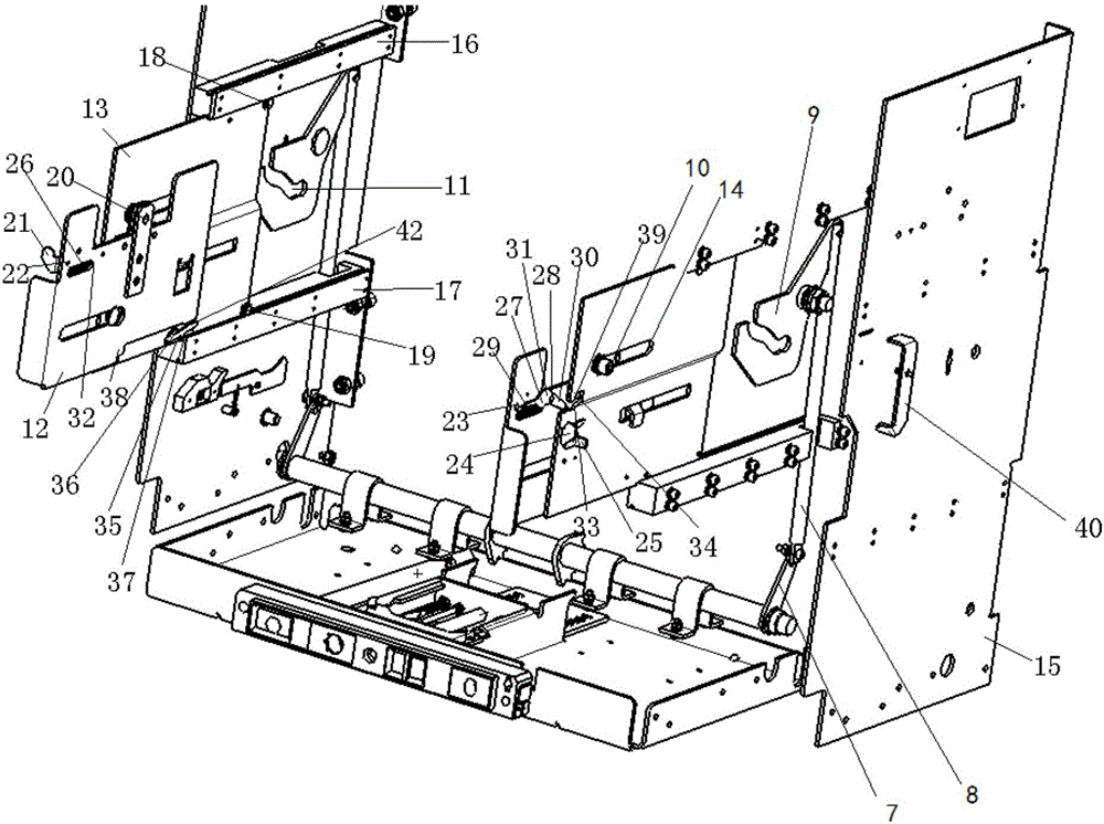
[0044] A drawer seat for switching appliances, such as figure 1 shown, including:

[0045] drawer frame;

[0046] The electrical connection mechanism is located in the frame of the drawer seat and is used to connect the main circuit of the switching device body;

[0047] Also includes:

[0048] The sliding mechanism is set in the frame of the drawer seat, and is used for fixing and entering and exiting the switch electrical body;

[0049] The transmission device is arranged in the frame of the drawer seat and connected with the sliding mechanism, and is used to drive the sliding m...


PUM


Abstract

The invention relates to a drawer holder for a switchgear comprising: a drawer holder frame, an electrical connection mechanism provided in the drawer holder frame for connecting the main circuit of the switchgear body; and a sliding mechanism provided in the drawer holder frame for fixing and going in and out of the switchgear body, and a transmission device provided in the drawer holder frame and connected with the sliding mechanism for driving the sliding mechanism to drive the switchgear body into and out. Compared with the prior art, the drawer holder applies the force exerted by the screw, the rack plate and the shaft to facilitate the fixing and the moving in and out of the switchgear body.

Description

technical field [0001] The invention relates to the field of low-voltage electrical appliances, in particular to a drawer seat for switching electrical appliances. Background technique [0002] The structure of the drawer switch is well known in the electrical industry. It is mainly composed of a drawer seat and a main body. When the main body needs maintenance or other operations, the main body can be shaken out from the drawer seat to separate the main circuit from the main circuit. Power-off operation, safe and reliable. [0003] Existing drawer seats for switching appliances, such as circuit breaker drawer seats, the force point when it drives the body into and out of the drawer seat is at the bottom of the drawer seat, and there is a tipping moment that makes the body rotate upward around the main axis, so the operator must It takes a relatively large force to overcome the resistance and realize the advancement or extraction of the main body. [0004] In the existing ...

Claims


Application Information

Patent Timeline
Patent Type & Authority Applications(China)
IPC IPC(8): H02B11/127H02B11/02
CPCH02B11/127H02B11/02
Inventor 周密崔伟王洋洋
Owner INST OF DONGGUAN TONGJI UNIV
Why Eureka
Try Eureka