Supercharge Your Innovation With Domain-Expert AI Agents!

Quiet electrical switch

A technology for electrical switches and electrical contacts, applied in the field of implementing switching mechanisms or bidirectional switching devices, electrical switches, can solve the problems of small size, reducing the switching speed of switching mechanisms, and the solution proves to be difficult to implement

Active Publication Date: 2018-09-28
LEGRAND SNC
View PDF4 Cites 0 Cited by
  • Summary
  • Abstract
  • Description
  • Claims
  • Application Information

AI Technical Summary

Problems solved by technology

[0014] However, this solution proved to be difficult to implement due to the need to mount an eccentric on the movable contact member, and since the movable contact member is implemented with expensive conductive materials, its dimensions are usually small
[0015] Also this proved unsatisfactory due to the slowness of the movable contact member over its entire travel, substantially reducing the switching speed of the switching mechanism

Method used


Image

  • Quiet electrical switch
  • Quiet electrical switch
  • Quiet electrical switch

Examples


Embodiment Construction

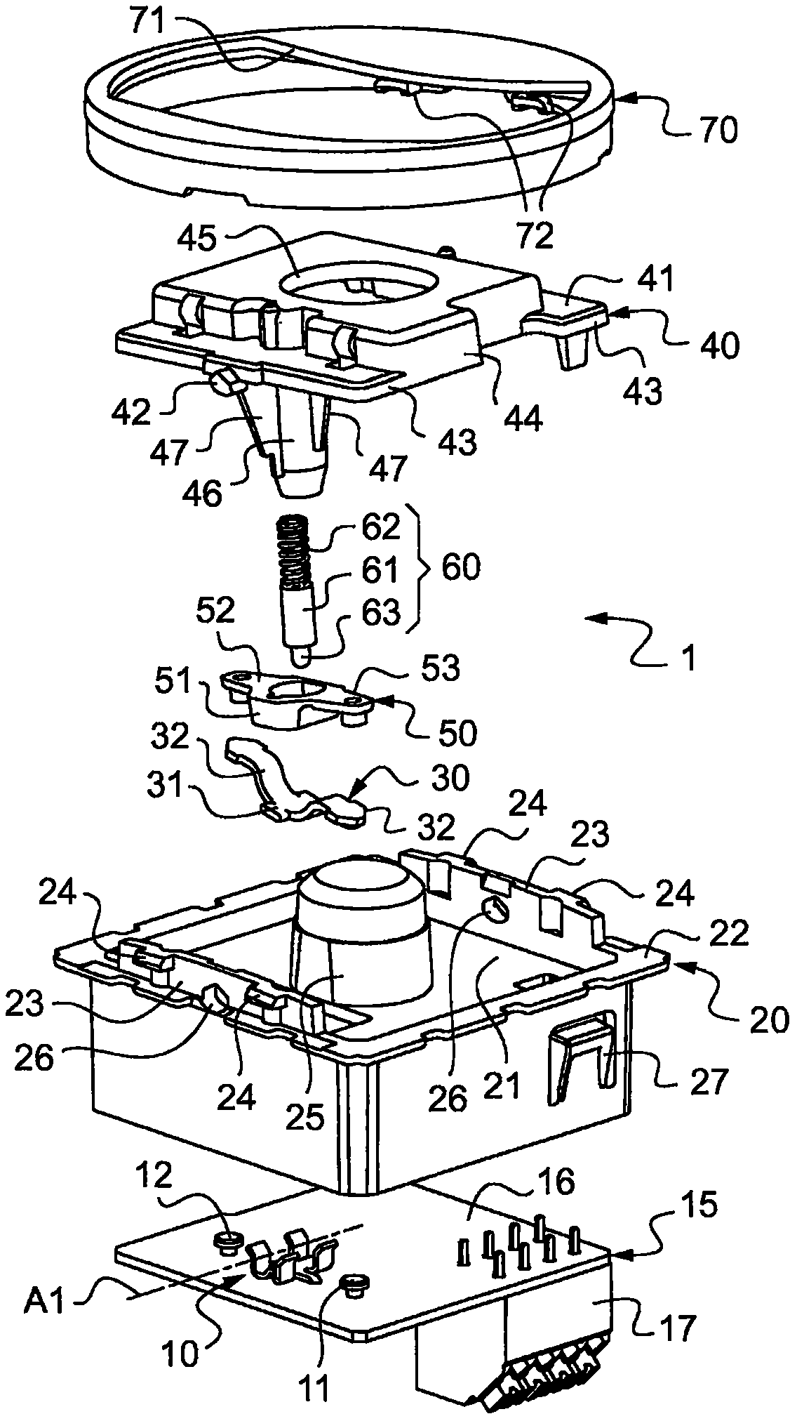
[0038] figure 1 An electrical switch 1 is shown in .

[0039] The electrical switch is here a device mechanism that can serve as a receptacle for a bidirectional switch.

[0040] The electrical switch 1 comprises an insulating box 20 accommodating two (in the case of a circuit breaker) or three (in the case of the present embodiment) fixed contact members 10 , 11 , 12 .

[0041] The insulating box 20 also houses a movable contact member 30 adapted to switch between two stable positions for breaking or establishing electrical contact between the different fixed contact members 10 , 11 , 12 .

[0042] The electrical switch 1 also has a control key 40 which is movably mounted relative to the insulating case 20 to control the displacement of the movable contact member 30 between the first and second stable positions.

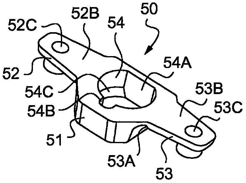
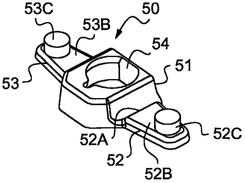
[0043] The electrical switch also comprises detent means 50 for the switching of the movable contact member 30 between two stable positions, which detent means ar...


PUM


Abstract

The invention relates to an electrical switch comprising: - two fixed contact members (10, 11); - a movable contact member (30), adapted in which it breaks said two fixed contacts switching between a first stable position of electrical contact between the members and a second stable position in which it establishes electrical contact between said two fixed contact members; - a control key for controlling the displacement of the movable contact member (40); - Braking means for slowing down the switching of the movable contact member. According to the invention, said brake device comprises a brake fitting (50), the support of which is fixed to the control key, the buffer of which is adapted to slow down the switching of said movable contact member.

Description

technical field [0001] The present invention generally relates to the field of electrical equipment. [0002] The present invention relates more particularly to electrical switches comprising: [0003] - at least first and second fixed contact members, which are fixed in the insulating box at a distance from each other, [0004] - a movable (movable, movable) contact member adapted to switch (turn over, rock) in the insulating case between a first stable position and a second stable position, in which the movable contact a member breaking electrical contact between said first and second fixed contact members, the movable contact member establishing electrical contact between said first and second fixed contact members in a second stable position, [0005] - a control key movably mounted relative to the insulating case for controlling displacement of the movable contact member between its first and second stable positions, and [0006] - Braking means slowing down (damping, ...

Claims


Application Information

Patent Timeline
Patent Type & Authority Patents(China)
IPC IPC(8): H01H3/60H01H23/16H01H23/24
CPCH01H3/60H01H23/168H01H23/24
Inventor A·巴鲁彻
Owner LEGRAND SNC
Features
  • R&D
  • Intellectual Property
  • Life Sciences
  • Materials
  • Tech Scout
  • Unparalleled Data Quality
  • Higher Quality Content
  • 60% Fewer Hallucinations
Learn More