
Wireless, internet-based medical-diagnostic system

a medical-diagnostic system and internet-based technology, applied in the field of wireless internet-based medical-diagnostic system for diagnosing patients, can solve problems such as inaccurate diagnoses, and achieve the effect of accurate diagnosis of patients

Active Publication Date: 2008-07-08
SOTERA WIRELESS
View PDF12 Cites 339 Cited by
  • Summary
  • Abstract
  • Description
  • Claims
  • Application Information

AI Technical Summary

Benefits of technology

[0009]In general, in one aspect, the invention features a wireless, internet-based medical device for remotely monitoring a patient. Specifically, it measures data characterizing a patient's vital signs, wirelessly transmits these data through a wireless network to an internet-accessible software piece, analyzes the data, and then avails the analyzed data over a web site hosted on the internet. A medical professional, such as a registered nurse working in a call center, can view and analyze these data in real-time to accurately diagnose the patient. In this way a thorough medical ‘appointment’ can be conducted over the telephone or Internet while the patient remains at home. A single medical professional can monitor hundreds of patients, each in separate remote site, using the Internet.
[0021]Different embodiments of the invention include one or more of the following advantages. They allow one or more medical professionals to remotely analyze a large group of patients accurately and in real-time. Patients can measure their vital signs and subsequently have these data monitored by a medical professional located thousands of miles away. Data measured with high frequency (e.g., several times each day) provide a relatively comprehensive data set compared to that measured during medical appointments separated by several weeks or even months. This allows both the patient and medical professional to observe trends in the data, such as a gradual increase or decrease in a particular vital sign, which may indicate a medical condition. And they minimize effects of white coat syndrome since the patient can make measurements at home or work.
[0022]Diabetic patients can use at least some of the embodiments to wirelessly transmit their blood glucose level after each measurement, making it unnecessary to record these data in a logbook. Patients with Internet access can view data analyzed with a variety of algorithms. Similarly, parents can remotely view data measured by their children. During medical appointments professionals can view the data and adjust a patient's exercise and diet to better control their diabetes. A call center staffed by medical professionals can use the invention to constantly monitor patients, such as patients with severe cardiac conditions, and quickly respond in the case of emergency.
[0024]An internet-based software system for medical diagnoses can also be easily updated and made available to a large group of users simply by updating software on the web site. In contrast, a comparable updating process for a series of in-hospital medical devices can only be accomplished by updating the software on each individual device. This, of course, is time-consuming, inefficient, and expensive, and introduces the possibility that many devices within a particular product line will not have the very latest software.
[0025]The device used to access and transmit the patient's data can be small, portable, and low-cost. Measurements are made in a matter of minutes and transmitted with a latency of a few seconds. A single device can also be used to measure and transmit data from multiple patients, provided it includes software and hardware that allows each patient to enter an identifying code that is, in turn, associated with their respective vital-sign data.

Problems solved by technology

For example, white coat syndrome can elevate a patient's heart rate and blood pressure; this, in turn, can lead to an inaccurate diagnoses.

Method used


Image

  • Wireless, internet-based medical-diagnostic system
  • Wireless, internet-based medical-diagnostic system
  • Wireless, internet-based medical-diagnostic system

Examples


Embodiment Construction

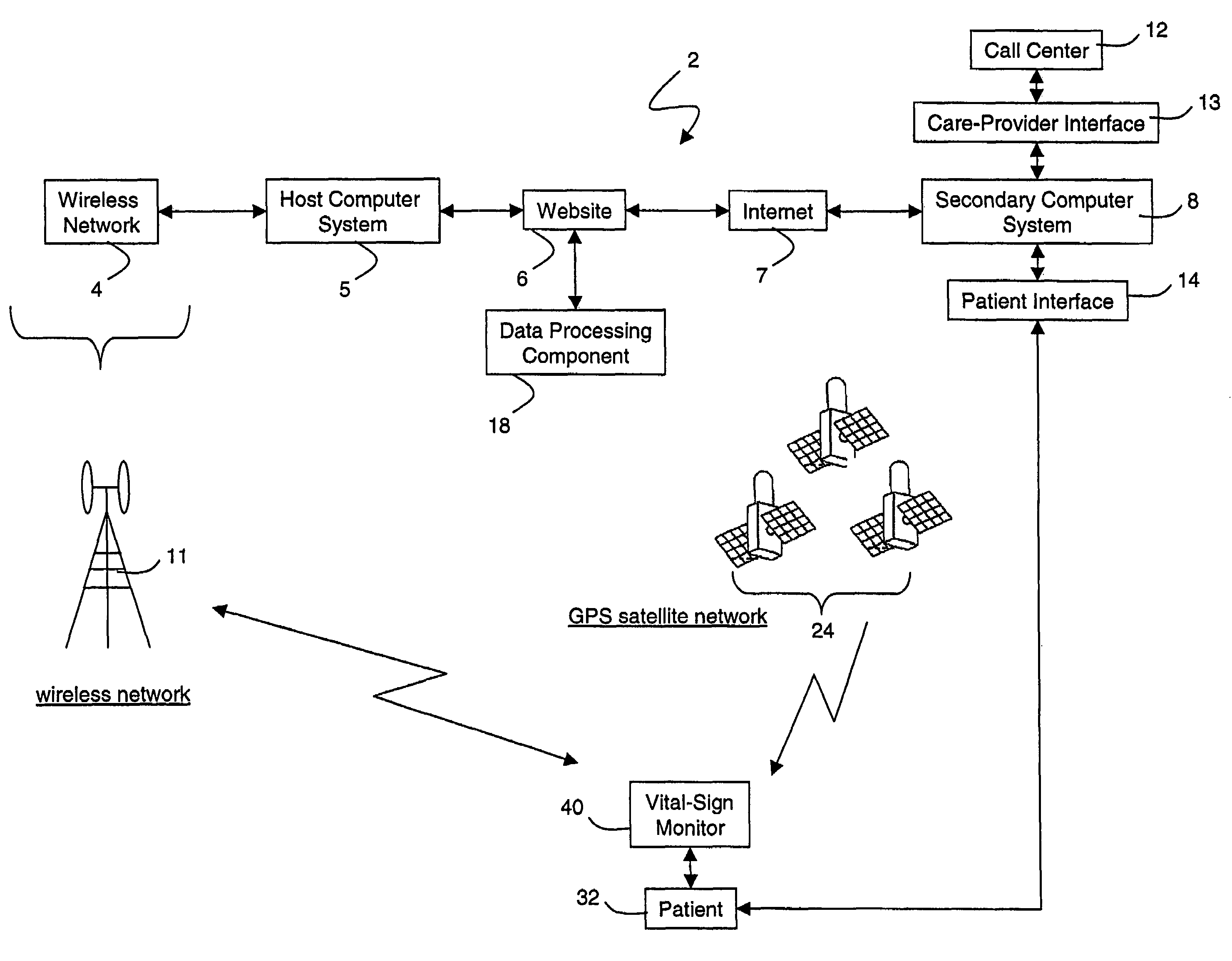
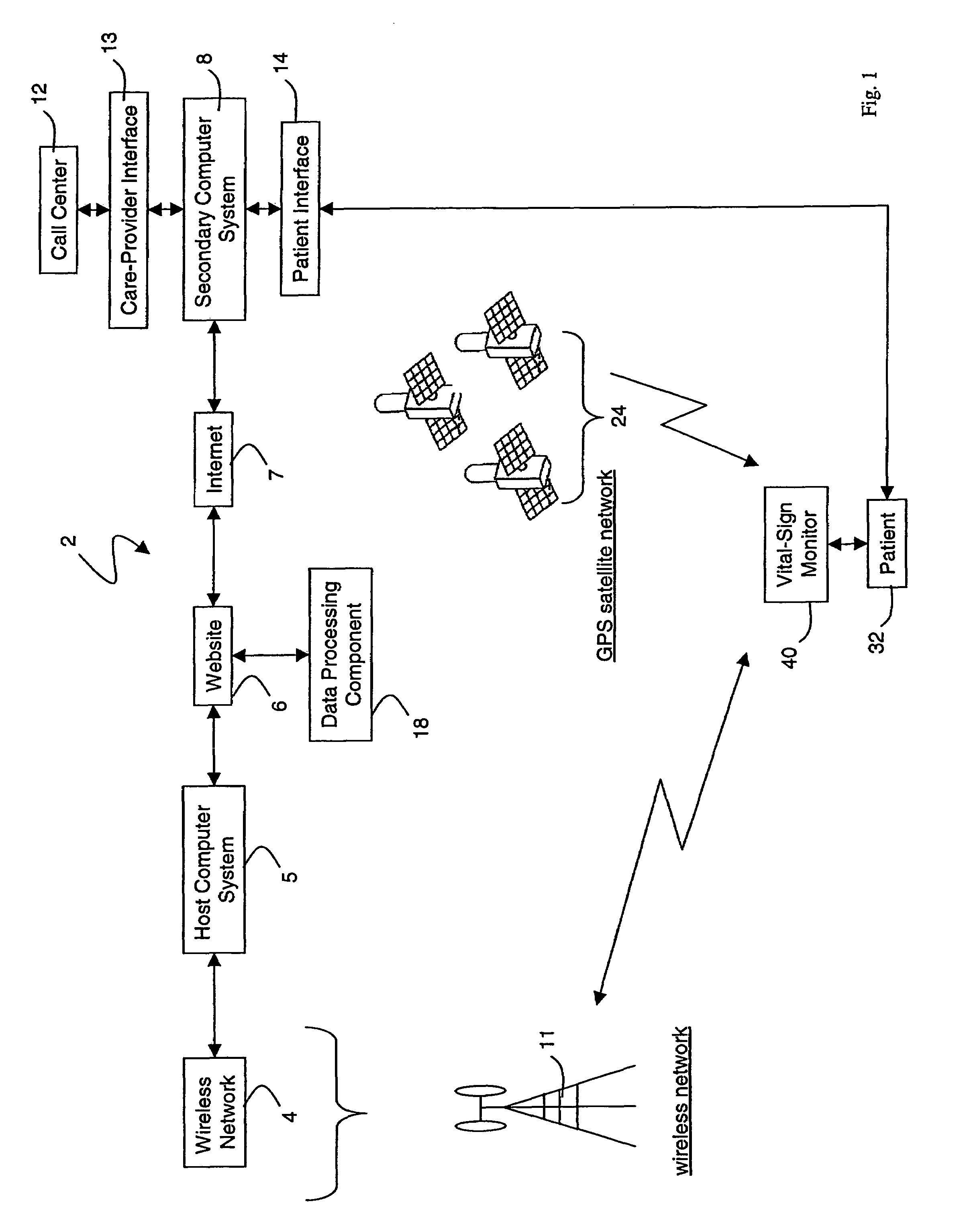
[0037]FIG. 1 shows a schematic drawing of an Internet-based medical-diagnostic system 2. The system 2 features a vital-signs monitor 40 that measures vital-sign data from a patient 32 and wirelessly transmits these data over a wireless network 4 to a web site 6 accessible through the Internet 7. The system 2 functions in a bi-directional manner, i.e. the vital-sign monitor 40 can both send and receive data. In typical operation, for example, the vital-sign monitor 40 predominantly transmits vital-sign data through the wireless network 4 to the web site 6. Using the same network, the monitor 40 also receives text-based instant messages (described with reference to FIG. 8) and software upgrades to function in a bi-directional manner.

[0038]The vital-sign monitor 40 includes systems that measure, e.g., blood pressure, O2 saturation, ECGs, heart rate, respiratory rate, and blood glucose level. After these data are measured, software in the monitor 40 formats them into a data packet. The ...


PUM


Abstract

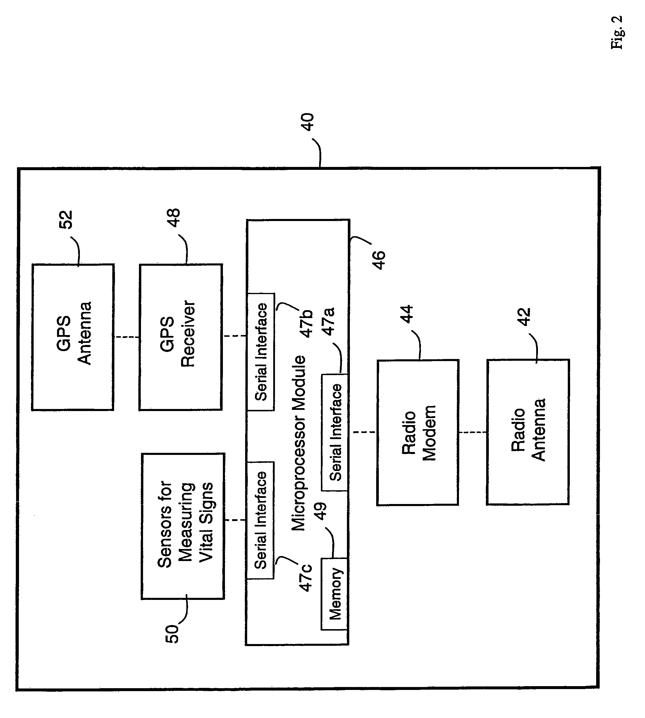
A system for monitoring a patient's vital signs that features a vital-sign monitor including sensors for measuring from the patient at least one of the following vital-sign data: O2 saturation, blood pressure, electro-cardiogram, respirator rate, and blood glucose level. The system also includes a global positioning system that determines location-based data. A wireless transmitter, in electrical contact with the vital-sign monitor and global positioning system, receives the vital-sign and location-based data and wirelessly transmits these data through a conventional wireless network. A gateway software piece receives and processes the data from the wireless network and stores these data in a computer memory associated with a database software piece. The system also includes an Internet-based user interface that displays the vital sign data for both individual patients and care-providers.

Description

[0001]This application claims the benefit of U.S. Provisional Application No. 60 / 438,442, filed Jan. 7, 2003.FIELD OF THE INVENTION[0002]The present invention features a wireless, internet-based system for diagnosing a patient.BACKGROUND OF THE INVENTION[0003]Medical professionals use a variety of medical devices to measure a patient's vital signs during a routine checkup. Such devices can measure, for example, blood pressure, blood oxygen saturation (called O2 saturation), electro-cardiograms, heart rate, respiratory rate, and blood glucose level. A sphygmomanometer measures blood pressure with an inflatable cuff and sensing electronics that determine the patient's systolic and diastolic blood pressure. Another medical device, called a pulse oximeter, clips to the patient's finger and measures the percentage of haemoglobin that is saturated with oxygen. To make this measurement, the pulse oximeter includes separate light sources (e.g. diode lasers or light-emitting diodes) that emi...

Claims


Application Information

Patent Timeline
Patent Type & Authority Patents(United States)
IPC IPC(8): A61B5/00A61B5/02
CPCA61B5/0022A61B5/745Y10S128/903A61B5/0205A61B5/0816A61B5/14551A61B2505/07G16H40/67A61B5/318
Inventor BANET, MATTHEWSCHULTZ, RANDONMURAD, ROBERT
Owner SOTERA WIRELESS
Learn More