Constant-current timing charger

A charger and rechargeable battery technology, applied in the electronic field, can solve the problems of the battery becoming garbage, waste, affecting battery capacity and life, etc.

Inactive Publication Date: 2017-03-01
CHONGQING NINGLAI SCI & TRADE
View PDF6 Cites 0 Cited by
  • Summary
  • Abstract
  • Description
  • Claims
  • Application Information

AI Technical Summary

Problems solved by technology

[0002] With the enrichment of modern life, there are more and more types of electrical appliances using batteries, such as security equipment, digital machines, mobile phones, etc. For this reason, there are also many types of chargers, but there is a lack of a low-carbon battery in these types. Various types of environmentally friendly charging circuits
The first significance is that the charging supervisor in the current product is the circuit transistor that stops charging and is easily damaged. Once damaged, the charger becomes garbage.
It is understood that this failure has become the main failure point, and it is a great waste to turn it into garbage just because of this damage. People are often lost)
The second significance is that during the charging process, the battery is not charged scientifically, so it affects the capacity and life of the battery. It is also easy to turn the battery into garbage prematurely, which forms waste and pollutes the environment
(Waste batteries pollute the environment)
The reason for not achieving the most scientific charging is that the current products either only use DC to charge the battery, but do not use a better method, such as constant current charging; or even though they can be charged with a constant current source , but there are still some conveniences in use, or it is not scientific enough on the line, etc., so it should be enriched and developed

Method used


Image

  • Constant-current timing charger
  • Constant-current timing charger
  • Constant-current timing charger

Examples


Embodiment Construction

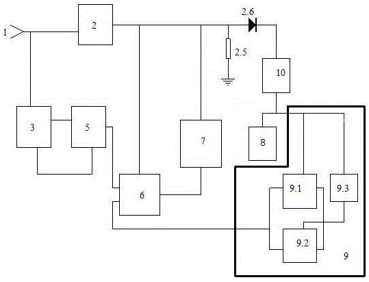
[0081] figure 1 , 2 , 3, 4, 5 examples of a constant current timing charger is an implementation of the workpiece example.

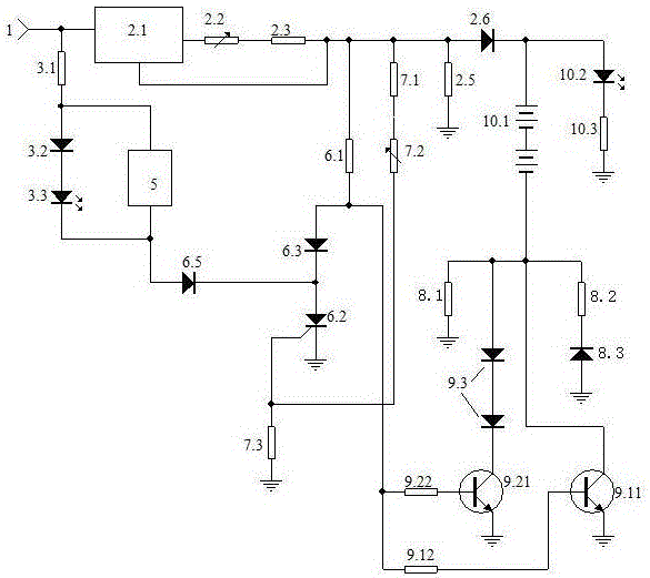
[0082] 1. Select components: the integrated circuit uses 78 series such as 7812, the triode adopts 8050, the sound chip in the sound body has no special requirements, the size of the piezoelectric ceramic chip in the sound body is determined according to the installation box, and the diode adopts surface-bonded diode , Adjustable resistance, and other resistance-capacitance parts have no special requirements.

[0083] 2. Making circuit boards and welding: press figure 2 The schematic diagram to make the circuit board, press figure 2 Schematic of soldered components.

[0084] The constant current voltage regulator is composed of a three-terminal voltage regulator circuit, a constant current adjustable resistor, and a constant current protection resistor: the input terminal of the three-terminal voltage regulator circuit is connected to the constant c...


PUM


Abstract

The invention discloses a constant-current timing charger, and belongs to the technical field of electronics. The charger consists of a constant-current stable voltage source, a drain resistor, a guide diode, a finishing indication unit, a sound control unit, a timing finishing unit, a sampling unit, a charging unit, a trickle circuit, and a load circuit. The constant-current stable voltage source supplies a constant current to the constant-current timing charger. The charging unit is provided with a working circuit, a charging standby circuit and a conversion circuit. When the working circuit is damaged, the charging standby circuit actively replaces the working current and forms a charging mode. When the charging of a charged battery in the load unit is finished, the sampling unit instantly starts the timing finishing unit, and the charging unit stops the charging. The finishing indication unit has a sound and light indication mode. Meanwhile, a trickle resistor in the trickle circuit provides a maintained trickle current grounding channel for the charged battery. According to the embodiment of the invention, the charger greatly prolongs the service life, reduces the rejection rate, achieves the scientific charging of the charged battery, improves the maintenance, and guarantees the service life of the charger and the charged battery.

Description

technical field [0001] It belongs to the technical field of electronic technology. Background technique [0002] With the enrichment of modern life, there are more and more types of electrical appliances using batteries, such as security equipment, digital machines, mobile phones, etc. For this reason, there are also many types of chargers, but there is a lack of a low-carbon battery in these types. Various types of environmentally friendly charging circuits. The first significance is that in current products, the charging director, which is the circuit transistor that stops charging, is easily damaged. Once damaged, the charger becomes garbage. It is understood that this failure has become the main failure point, and it is a great waste to turn it into garbage just because of this damage. People are often lost). The second significance is that during the charging process, the battery is not charged scientifically, so it affects the capacity and life of the battery. It i...

Claims


Application Information

Patent Timeline
Patent Type & Authority Applications(China)
IPC IPC(8): H02J7/00
Inventor 宁永敭
Owner CHONGQING NINGLAI SCI & TRADE
Why Eureka
Try Eureka