Spiral compression spring damper with presettable rigidity

A technology of compressing springs and dampers, which is applied in the field of damping devices for coil springs, can solve the problems of long dampers, waste of resources, shortened effective working length of springs, etc., and achieve the effect of shortening the length and reducing the cost of shock isolation

Inactive Publication Date: 2017-03-08
NANJING DADE DAMPING TECH CO LTD
View PDF9 Cites 0 Cited by
  • Summary
  • Abstract
  • Description
  • Claims
  • Application Information

AI Technical Summary

Problems solved by technology

However, this utility model patent obviously has the following disadvantages: 1. Two cylindrical coil springs are required, and the length of the entire damper is relatively long, which is not suitable for installation in a space with a small distance; 2. It is impossible or even impossible to guarantee The stiffness of the two springs (including tensile stiffness and compression stiffness) are equal, so the shock absorption effect is different in different wind directions; 3. The stiffness of the damper cannot be changed to achieve the preset wind resistance level and reduce the cost of shock absorption; 4. A cylindrical coil spring works in two states of tension and compression at the same time. The metal material and production process of the existing spring are difficult to meet the requirements. The stretching and compression can only be realized by reducing the elastic deformation range of the cylindrical coil spring. Two working states, which will obviously cause waste of resources
It can be seen that although the stiffness of the spring in the patent application scheme can be changed, the effective working length of the spring is not only significantly shortened, but also can only be compressed for energy consumption and vibration reduction, and cannot be stretched for energy consumption and vibration reduction.

Method used


Image

  • Spiral compression spring damper with presettable rigidity
  • Spiral compression spring damper with presettable rigidity
  • Spiral compression spring damper with presettable rigidity

Examples


example 1

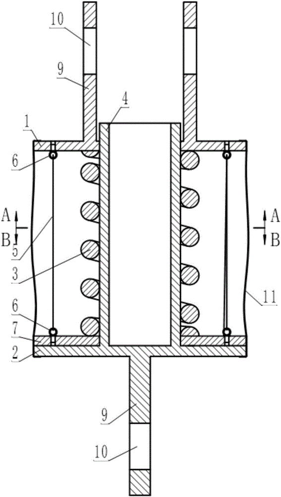
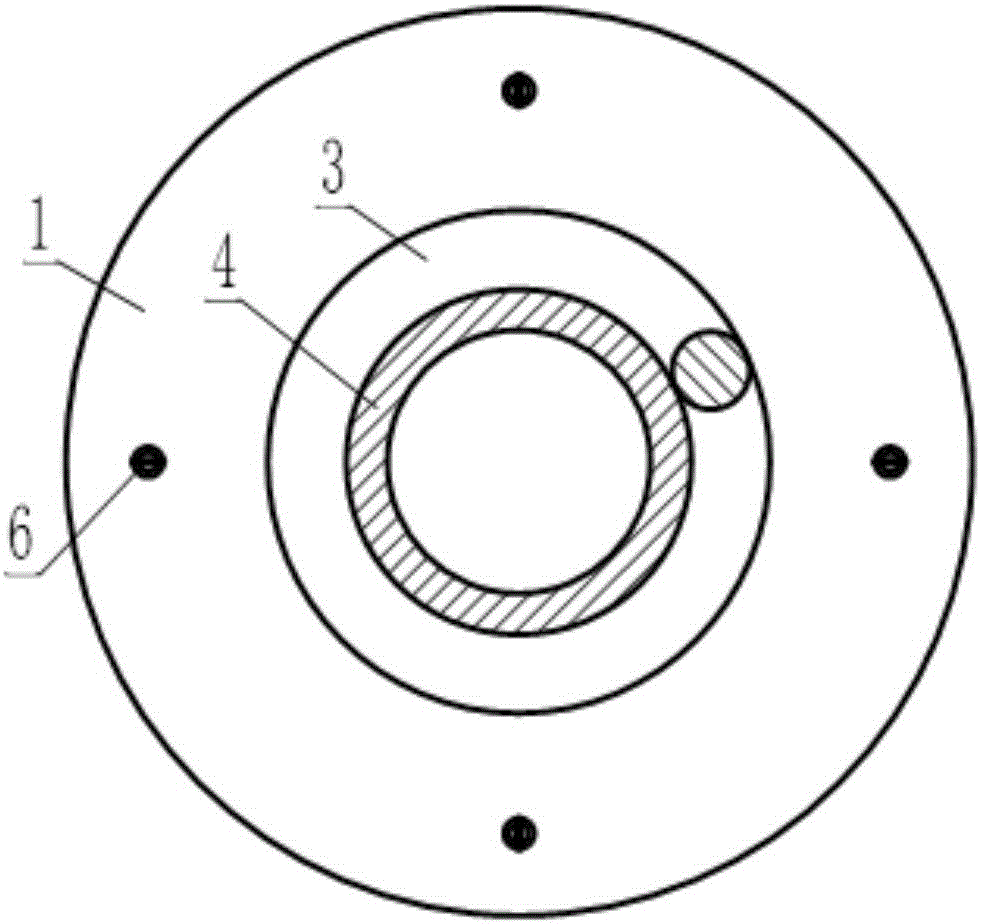
[0036] see Figure 1~3 , this example is a damper used for seismic reinforcement of building structures, the damper includes a disc-shaped upper end plate 1 and a lower end plate 2, a cylindrical helical compression spring 3 is arranged between the upper and lower end plates, wherein the lower end plate 2 A guide rod 4 is arranged on it, and the guide rod 4 passes through the upper end plate 1 upwardly along the central hole of the cylindrical helical compression spring 3 .

[0037] see Figure 1~4 , There is also a back pressure device between the upper and lower end plates, and the back pressure device includes four preloaded steel wire ropes 5, four eyebolts 6 as wire rope direction changing elements and a floating back pressure steel plate 7.

[0038] see figure 1 , image 3 and Figure 4 , The floating anti-pressure steel plate 7 is sleeved on the guide rod 4 between the cylindrical helical compression spring 3 and the lower end plate 2 .

[0039] see figure 1 and ...

example 2

[0046] This example is also a damper used for anti-seismic reinforcement of building structures. The main difference between this damper and the damped vibrator described in Example 1 is that the back pressure device is different. The counter pressure device of this example will be described below.

[0047] see Figure 5-10 , the back pressure device in this example is located between the upper end plate 1 and the lower end plate 2, and the back pressure device includes four preloaded steel wire ropes 5, four U-shaped members 12 as steel wire rope direction changing elements and a floating back pressure steel plate 7 .

[0048] see Figure 5 , Figure 6 and Figure 9 , The floating anti-pressure steel plate 7 is sleeved on the guide rod 4 between the cylindrical helical compression spring 3 and the upper end plate 1 .

[0049] see Figure 5 , Figure 7 and Figure 8 , four U-shaped members 12 serving as wire rope redirection elements are fixed on the lower end plate 2 ...

example 3

[0056] see Figures 11-15 , the damper described in this example is a kind of vertical shock-isolation device (also called vertical shock-isolation support) for building anti-seismic, it comprises disc-shaped upper end plate 1 and lower end plate 2, upper and lower end plate A cylindrical helical compression spring 3 is arranged between them, wherein a guide rod 4 is provided on the upper end plate 1 , and the guide rod 4 passes through the lower end plate 2 upwardly along the center hole of the cylindrical helical compression spring 3 .

[0057] see Figure 11 , the edges around the upper end plate 1 and the lower end plate 2 are respectively provided with six installation holes 14, wherein the lower end plate 2 is an upside-down washbasin shape formed by the middle part upwards, and the center is provided with a hole matching the guide rod 4.

[0058] see Figures 11-15 , A back pressure device is provided between the upper and lower end plates, and the back pressure device ...


PUM


Abstract

The invention relates to a spiral compression spring damper with presettable rigidity, characterized in that a back pressure device is also arranged between two end plates and comprises more than three prestressed wire ropes, wire rope direction-varying elements as many as the prestressed wire ropes, and a floating back pressure steel plate, wherein the prestressed wire ropes are distributed around a cylindrical spiral compression spring in a broken line form, one ends of the prestressed wire ropes are fixed to the floating back pressure steel plate symmetrically around the axis of a guide rod, and the other end of each prestressed wire rope is passed through the opposing wire rope direction-varying element and returned, and is passed through the floating back pressure steel plate near a fixation point of such prestressed wire rope on the floating back pressure steel plate and then fixed to the end plate adjacent to the floating back pressure steel plate; the prestressed wire ropes are tensioned to tension required by preset initial rigidity, such that the cylindrical spiral compression spring is clamped between the end plate, far away from the floating back pressure steel plate, and the floating back pressure steel plate.

Description

technical field [0001] The invention relates to a building anti-vibration (or vibration) device, in particular to a coil spring damping device. Background technique [0002] A damper is a device that provides resistance to movement and consumes movement energy. Since the 1970s, dampers have been gradually transferred from industries such as aerospace, aviation, military, guns, and automobiles to structural engineering such as buildings, bridges, and railways. Coil springs are widely used in devices such as shock isolation and shock absorption due to their variable stiffness characteristics in which the load and deformation are linearly related. Coil springs are classified according to the method of use, mainly including extension springs and compression springs, among which cylindrical helical compression springs are most commonly used in dampers. However, a specific cylindrical helical compression spring can only work in a compressed state within the effective working ran...

Claims


Application Information

Patent Timeline
IPC IPC(8): E04H9/14E04H9/02
CPCE04H9/02E04H9/14
Inventor 谢韩涛刘汶津韩磊张少华
Owner NANJING DADE DAMPING TECH CO LTD
Why Eureka
Try Eureka