Rubber air spring damper capable of presetting initial rigidity

A rubber air spring and initial stiffness technology, which is applied in the field of damping devices containing rubber air springs, can solve the problems of reducing the cost of shock absorption, waste of resources, and the inability to change the early stiffness of the damper, so as to reduce the cost of shock isolation and shorten the length. Effect

Active Publication Date: 2017-02-22
NANJING DADE DAMPING TECH CO LTD
View PDF9 Cites 0 Cited by
  • Summary
  • Abstract
  • Description
  • Claims
  • Application Information

AI Technical Summary

Problems solved by technology

However, this utility model patent obviously has the following disadvantages: 1. Two coil springs are required, and the length of the entire damper is relatively long, which is not suitable for installation in a space with a small distance; 2. It is difficult or even impossible to ensure the two springs in the process Only the stiffness of the spring (including tensile stiffness and compression stiffness) is equal, so the shock absorption effect is different in different wind directions; 3. The early stiffness of the damper cannot be changed to achieve the preset wind resistance level and reduce the cost of shock absorption; 4. A helical spring works in two states of tension and compression at the same time. The metal material and production process of the existing spring are difficult to meet the requirements. The two working states of tension and compression can only be realized by reducing the elastic deformation range of the helical spring. , which obviously wastes resources
Since the rubber air spring is a closed air chamber whose main body is made of rubber, the above three means of changing the effective working length of the spring are obviously not suitable for the rubber air spring; , and can only compress energy-dissipating vibrations, but not stretch energy-dissipating vibrations

Method used


Image

  • Rubber air spring damper capable of presetting initial rigidity
  • Rubber air spring damper capable of presetting initial rigidity
  • Rubber air spring damper capable of presetting initial rigidity

Examples


example 1

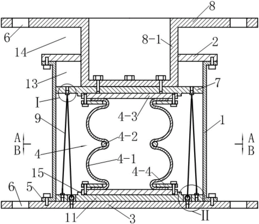
[0040] see Figure 1-5 , the damper described in this example is a vertical shock-isolation device (also known as a vertical shock-isolation support) for building anti-seismic, which includes a guide sleeve 1, a first end cover 2, a second end cover 3 , Rubber air spring 4 and back pressure device.

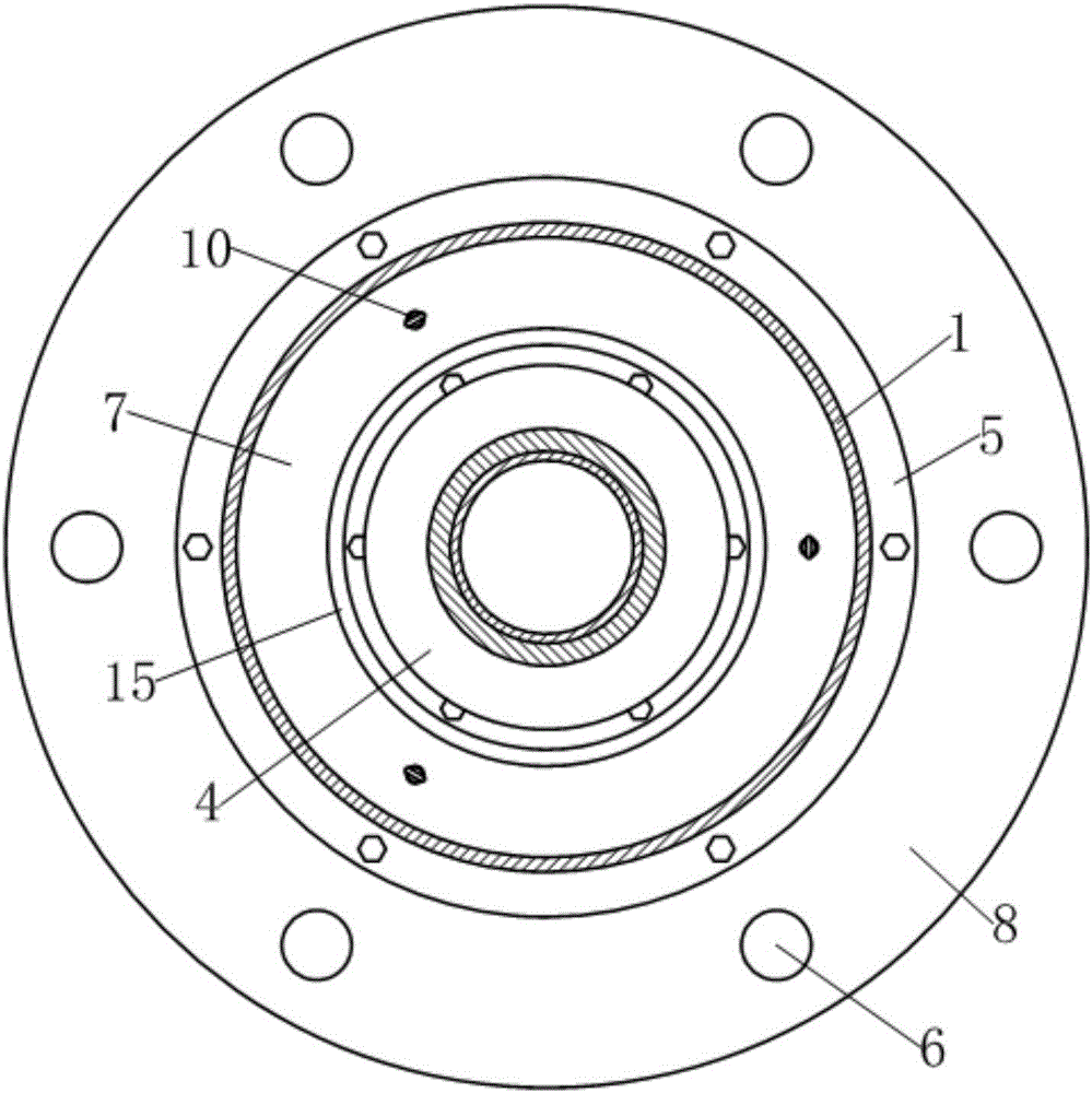
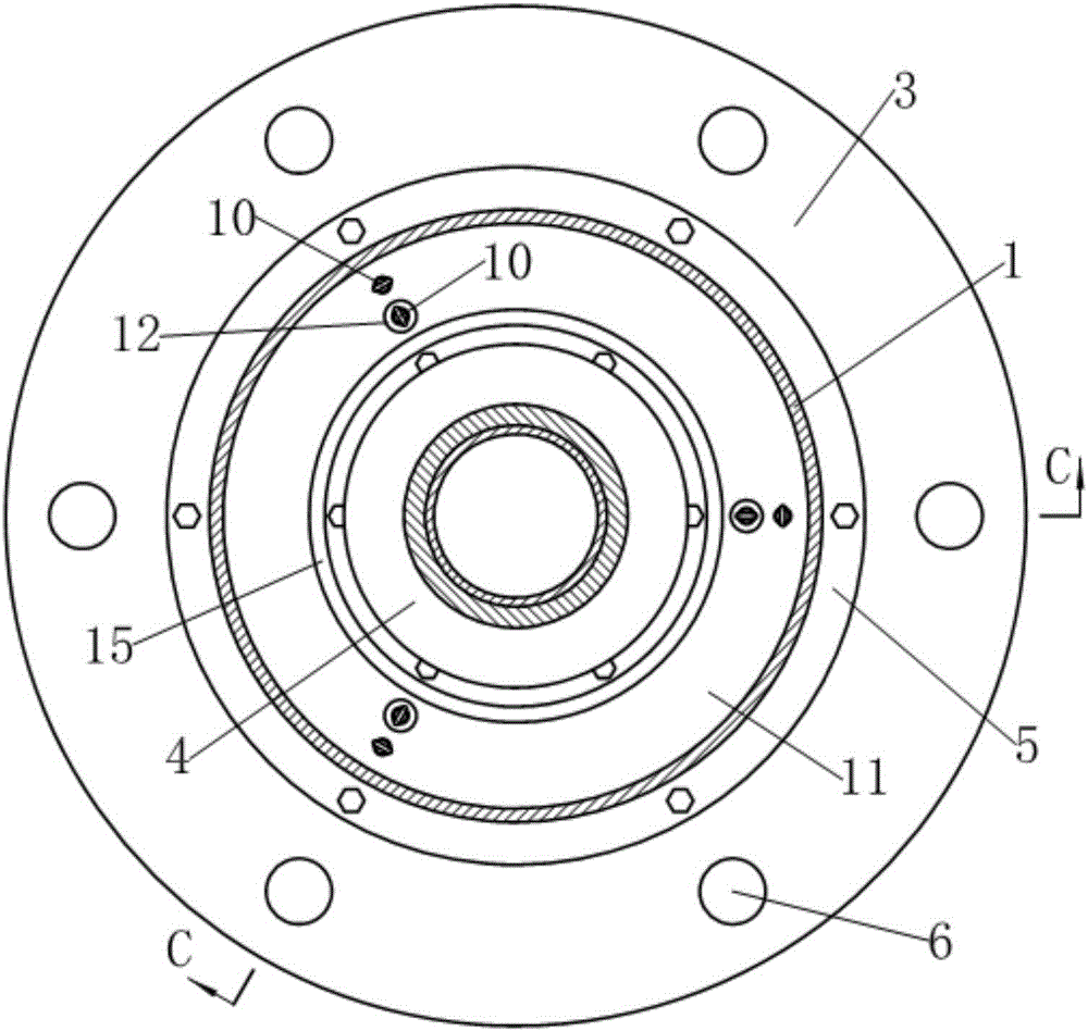
[0041] see Figure 1~3 , the guide sleeve 1 is in the shape of a circular tube, and its two ends extend radially outward to form a flange 5 . The first end cover 2 is connected to the flange 5 on the upper end of the guide sleeve 1, and the center is provided with a guide hole; the second end cover 3 is disc-shaped, and the surrounding edges are provided with mounting holes 6. The guide sleeve 1 is fixed on the middle part of its upper surface by the flange plate 5 provided at the lower end.

[0042] see Figure 1~3 , the driving member is composed of a dynamic pressure plate 7 and an upper connecting plate 8, wherein the edge of the upper connecting plate 8 is provided with a ...

example 2

[0055] see Figure 6-11 , the damper described in this example is also a vertical shock-isolation device for building anti-seismic, and on the basis of example 1, the following improvements are mainly made: (1) the pre-compressed steel wire rope 9 is increased by three to four; (2) replace the eye screw 10 as the wire rope changing element with a U-shaped member 17; (3) replace the eye screw 10 at the other end of the fixed preloaded wire rope 9 with a wire rope self-locking anchor 16; (4 ) thicken the middle part of the second end cover 3 and bulge upwards to form an inverted washbasin shape, so as to install the wire rope self-locking anchor 16; (5) correspondingly change the described back pressure device to:

[0056] The anti-pressure device consists of four pre-compressed steel wire ropes 9, four U-shaped members 17 as wire rope direction-changing elements, a floating counter-pressure steel plate 11, four eyebolts 10 for fixing one end of the pre-compressed steel wire rop...

example 3

[0065] see Figures 12 to 14 , this example is a damper used for seismic reinforcement of building structures, the damper includes a guide sleeve 1, the two ends of the guide sleeve 1 are respectively fixed with a first end cover 2 and a second end cover 3, and rubber air is provided inside Spring 4, a driving member extends from the center of the first end cover 2 at one end of the guide sleeve into the guide sleeve 1 and presses on the rubber air spring 4; wherein the driving member is formed by a dynamic pressure plate 7 and connected with it An integral first driving rod 18 is formed, and the end of the first driving rod 18 is provided with a connecting ring 18-1 which is screwed together with it, and the connecting ring 18-1 is provided with a hinge hole 19. The pressing plate 7 is in dynamic cooperation with the guide sleeve 1. The outer diameter of the rubber air spring 4 is smaller than the inner diameter of the guide sleeve 1, forming an annular space between the two...


PUM


Abstract

The invention relates to a rubber air spring damper capable of presetting initial rigidity. The rubber air spring damper is characterized in that a back pressure device is arranged in a guide sleeve; the back pressure device includes more than three prepressing steel wire ropes, steel wire rope turning elements equal to the prepressing steel wire ropes in number and a floating back pressure steel plate, wherein the prepressing steel wire ropes are distributed in annular space between the guide sleeve and a rubber air spring in a folding state; one ends of all the prepressing steel wire ropes are symmetrically fixed on the floating back pressure steelplate around the axis of the guide sleeve, and the other ends are returned after penetrating through the corresponding steel wire rope turning elements, and are fixed on a second end cover after penetrating through the floating back pressure steel plate beside the fixed points of the prepressing steel wire ropes on the floating back pressure steel plate; and the prepressing steel wire ropes are tensioned to reach the tension needed by initial rigidity presetting, so that the rubber air spring is always clamped between a driving component and the floating back pressure steel plate.

Description

technical field [0001] The invention relates to a building anti-vibration (or vibration) device, in particular to a damping device containing a rubber air spring. Background technique [0002] The rubber air spring is a curved capsule formed by laminating rubber and network cables. The two ends of the capsule are sealed with two steel plates to form a compressed air chamber, which uses the compressibility of the air to achieve elastic action; due to the non-linear nature of the rubber air spring characteristics, and low natural frequency, it is widely used as a vibration isolation component in some high-frequency vibration occasions, such as automobiles, high-frequency machinery and building structures. [0003] For the design of anti-seismic structures, especially the anti-seismic structures of high-rise buildings, people pursue a comprehensive anti-seismic performance that combines "resistance" and "consumption", that is, under the action of weak wind vibration and small e...

Claims


Application Information

Patent Timeline
Patent Type & Authority Applications(China)
IPC IPC(8): F16F13/00
CPCF16F13/002
Inventor 谢韩涛刘汶津韩磊张少华
Owner NANJING DADE DAMPING TECH CO LTD
Why Eureka
Try Eureka