a door lever

A door suction and rod shaft technology, applied in the field of door suction rods, can solve the problems of no buffering effect, door damage, damage, etc., and achieve the effects of simple and reliable connection structure, saving use cost, and slowing impact force.

Active Publication Date: 2017-12-22
山东酷品智能科技有限公司
View PDF4 Cites 0 Cited by
  • Summary
  • Abstract
  • Description
  • Claims
  • Application Information

AI Technical Summary

Problems solved by technology

[0002] At present, the use and installation of doors has become an important part of home decoration and is closely related to people's lives. When people open the door with too much force, if things go on like this, the door will cause damage to the wall, and the door itself will collide with the wall. Damage will also occur after the door. For this reason, a door stopper is usually installed on the wall behind the door. The existing door stopper is only fixed on the wall by a push rod, thereby preventing the door from directly contacting the wall. Reduce the damage to the wall, but this kind of door stopper does not have a buffering effect. When people open the door with too much force, it will still cause the door to collide with the ejector rod, which will cause damage to the door, and the ejector rod is fixed. Has a buffering effect, so it cannot meet existing usage needs

Method used


Image

  • a door lever
  • a door lever
  • a door lever

Examples


Embodiment Construction

[0020] The following will clearly and completely describe the technical solutions in the embodiments of the present invention with reference to the accompanying drawings in the embodiments of the present invention. Obviously, the described embodiments are only some, not all, embodiments of the present invention. Based on the embodiments of the present invention, all other embodiments obtained by persons of ordinary skill in the art without making creative efforts belong to the protection scope of the present invention.

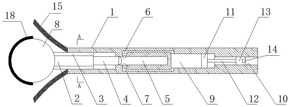
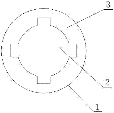
[0021] see Figure 1-4 As shown, a door suction rod of the present invention includes a clamping case 1 and a suction head body 8, the right end of the suction head body 8 is connected with a rod shaft 2, and the outer surface of the suction head body 8 is provided with a rubber anti-collision sleeve 18, The rubber anti-collision sleeve 18 is covered on the left half of the suction head body 8, and the rubber anti-collision sleeve 18 is glued and fixed with th...


PUM


Abstract

The invention discloses a door sucking rod. The door sucking rod comprises a clamping shell (1) and a sucker body (8); the right end of the sucker body (8) is connected with a rod shaft (2); a rubber anti-collision sleeve (18) is arranged on the outer surface of the sucker body (8), coats the left half part of the sucker body (8), and is fixedly glued with the sucker body (8); the rod shaft (2) is connected with the clamping shell (1) through a stretching structure (3); a buffer shaft (4) is arranged in the center position of the right end of the rod shaft (2); a buffer space (5) for placing the buffer shaft (4) is formed in the clamping shell (1); an air pressing space (9) is formed in the clamping shell (1) on the right side of the buffer space (5); a passing cavity (6) for communicating the air pressing space (9) with the buffer space (5) is arranged between the air pressing space (9) and the left edge part of the buffer space (5); and the passing cavity (6) is provided with a set of ejecting heads (7) at the left edge part of the buffer space (5).

Description

technical field [0001] The invention relates to a door suction rod. Background technique [0002] At present, the use and installation of doors has become an important part of home decoration, which is closely related to people's lives. When people open the door with too much force, if things go on like this, the door will cause damage to the wall, and the door itself will collide with the wall. Damage will also occur after the door. For this reason, a door stopper is usually installed on the wall behind the door. The existing door stopper is only fixed on the wall by a push rod, thereby preventing the door from directly contacting the wall, thereby Reduce the damage of the wall, but this kind of door stopper does not have a buffering effect. When people open the door with too much force, it will still cause the door to collide with the ejector rod, which will cause damage to the door, and the ejector rod is fixed. It has a buffering effect, so it cannot meet the existing u...

Claims


Application Information

Patent Timeline
Patent Type & Authority Patents(China)
IPC IPC(8): E05C17/46E05F3/02E05F5/02
CPCE05C17/46E05F3/02E05F5/02
Inventor 黄志凌
Owner 山东酷品智能科技有限公司
Why Eureka
Try Eureka