
A sealing structure, an oil cylinder and a wind generator

A sealing structure and sealing ring technology, applied in mechanical equipment, fluid pressure actuating devices, etc., can solve the problems of short service life, high failure rate of wind turbines, easy oil leakage, etc., and achieve long service life and reduce temperature rise. , the effect of improving the service life

Active Publication Date: 2018-07-13
SANY ELECTRIC CO LTD
View PDF6 Cites 0 Cited by
  • Summary
  • Abstract
  • Description
  • Claims
  • Application Information

AI Technical Summary

Problems solved by technology

[0005] One of the objects of the present invention is to provide a sealing structure, aiming to solve the problem of short service life of the sealing structure in the prior art
[0006] The second purpose of the present invention is to provide an oil cylinder, aiming to solve the problem of easy oil leakage during the use of high-frequency and high-frequency oil cylinders in the prior art
[0007] The third purpose of the present invention is to provide a wind power generator, aiming to solve the problem of high failure rate of wind power generators in the prior art

Method used


Image

  • A sealing structure, an oil cylinder and a wind generator
  • A sealing structure, an oil cylinder and a wind generator
  • A sealing structure, an oil cylinder and a wind generator

Examples


Embodiment 1

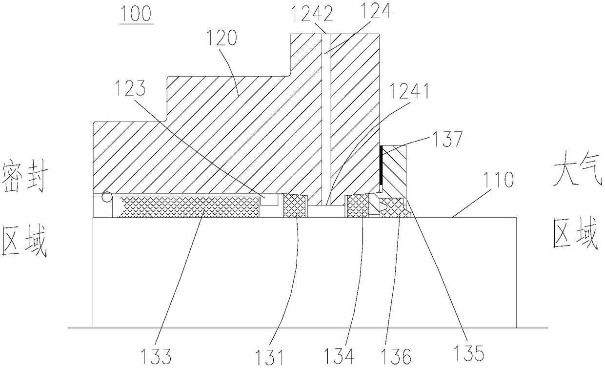
[0076] This embodiment provides an oil cylinder 200, please refer to figure 1 and Figure 11 , the oil cylinder 200 includes a cylinder block 210, a piston rod 110 and a guide sleeve 120, the guide sleeve 120 is fixed and sealed with the cylinder block 210, the piston rod 110 and the guide sleeve 120 form a piston rod assembly, and the sealing structure 100 is used for the piston rod 110 and the guide The seal of the sleeve 120 is connected. The inner side of the oil cylinder 200 is the sealing area, and the outer side of the oil cylinder 200 is the atmospheric area.

[0077] like figure 1 As shown, the sealing structure 100 includes a support ring 133 , a first sealing ring 131 , a second sealing ring 134 and a gland 135 .

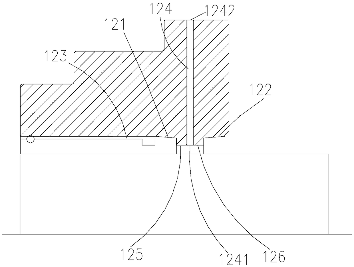
[0078] like figure 1 and figure 2 As shown, the guide sleeve 120 is a revolving structure, its outer side is a stepped structure, and its inner side is distributed along its axis direction with an annular first mating surface 121 and a second mating...

Embodiment 2

[0097] This embodiment provides a wind power generator (not shown in the figure), and the wind power generator applies the oil cylinder 200 in the first embodiment. The wind turbine using this oil cylinder 200 has a good sealing effect during operation. The wear and tear mileage of the oil cylinder 200 can reach tens of thousands of kilometers. It can be taken away quickly and improve the service life of the wind turbine.


PUM


Abstract

The invention provides a sealing structure, an oil cylinder and a wind driven generator, and belongs to the field of sealing structures. The sealing structure is applied to a piston rod assembly; a sealing region with relatively high pressure and an atmosphere region with relatively low pressure are respectively formed at two ends of the piston rod assembly; the piston rod assembly comprises a piston rod and a guide sleeve; the sealing structure comprises a first sealing ring; the piston rod and the guide sleeve are hermitically connected with each other through the first sealing ring; the first sealing ring is provided with a first side surface close to the piston rod and a second side surface close to the guide sleeve; the first sealing ring is further provided with a first end surface close to the sealing region and a second end surface close to the atmosphere region; the second side surface is a slope, and the outer diameter of the second end surface is less than that of the first end surface; and the inner side of the guide sleeve is provided with a first matching surface consistent with the tilting direction of the second side surface. The oil cylinder applies the sealing structure. The wind driven generator applies the oil cylinder. The oil cylinder has the characteristic of good sealing effect under a complicated working condition. The wind driven generator has the advantage of long service life.

Description

technical field [0001] The invention relates to the field of sealing structures, in particular, to a sealing structure, an oil cylinder and a wind generator. Background technique [0002] The sealing structure is one of the most commonly used structures in various fields. The common sealing structure is used at the connection between the rod and the sleeve to prevent the leakage of fluid, gas or solid particles from the adjacent joint surfaces, and to prevent external impurities such as dust and moisture. wait for intrusion. The common sealing structure cannot achieve a good sealing effect under complex working conditions, and substances are prone to leakage through the adjacent joint surfaces of the sealing structure. [0003] For example, in the oil cylinder, the piston rod and the guide sleeve are sealed and connected by a sealing structure, and the sealing structure is generally composed of rubber parts. It has a short service life and is prone to oil leakage. [0004...

Claims


Application Information

Patent Timeline
Patent Type & Authority Patents(China)
IPC IPC(8): F15B15/14F15B15/20
CPCF15B15/1461F15B2215/30
Inventor 孙丹康磊周现奇
Owner SANY ELECTRIC CO LTD
Learn More