A method of chipping in grooves of electronic products

A technology in electronic products and grooves, used in electrical components, electrical components, etc., can solve the problems of non-flat structure, different grooves, and low precision in the film area of ​​the shielding cover, so as to improve product quality and reduce defective rates. , the effect of high cleanliness

Active Publication Date: 2019-07-09
HANGZHOU HAIZE ELECTRONICS TECH CO LTD
View PDF5 Cites 0 Cited by
  • Summary
  • Abstract
  • Description
  • Claims
  • Application Information

AI Technical Summary

Problems solved by technology

In these electronic products, the back cover is generally set as a shield, and the shield is generally not a regular planar shape, but a cover with a groove inside. At the same time, depending on the product, the depth or shape of the groove varies. The same, in addition, there are often through holes or some socket holes for setting the camera on the shielding cover, which leads to the non-flat structure of the inner film area of ​​the shielding cover.
[0003] These electronic products need to be placed in the groove of the shielding cover before leaving the factory. The general patch is a single-sided adhesive with special properties. The current method is to manually paste the cut patch in the groove, and the The cut patch is generally directly bonded to the negative. Before pasting, the patch needs to be picked up with tweezers and pasted into the groove. Note that sometimes there must be a certain gap between the patch and the four sides of the groove, so that the manual The accuracy of the gap left is not high, and the paste cannot be guaranteed to be straight, the production capacity is low, and the defective rate is high

Method used


Image

  • A method of chipping in grooves of electronic products
  • A method of chipping in grooves of electronic products
  • A method of chipping in grooves of electronic products

Examples


Embodiment

[0029] A method for placing a patch in a groove of an electronic product, comprising the following steps:

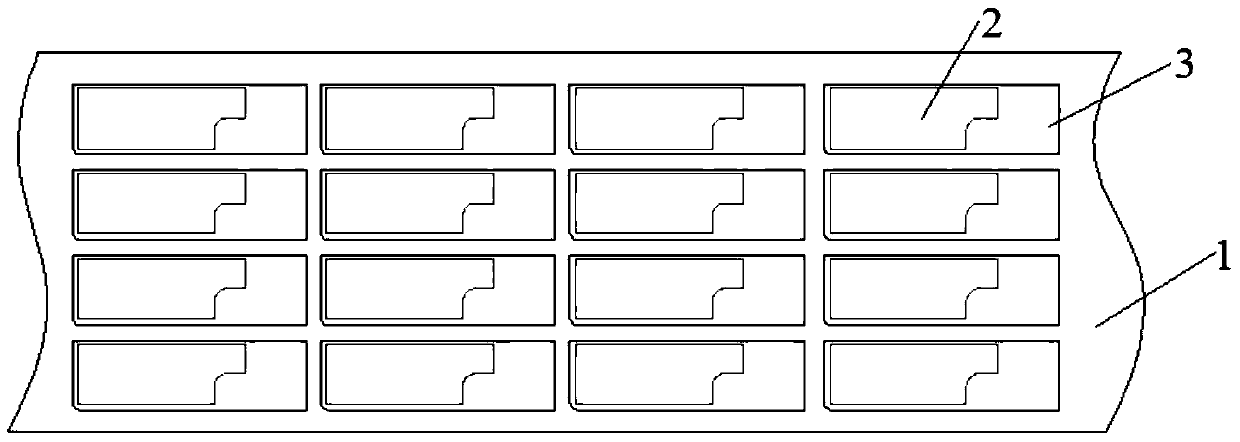
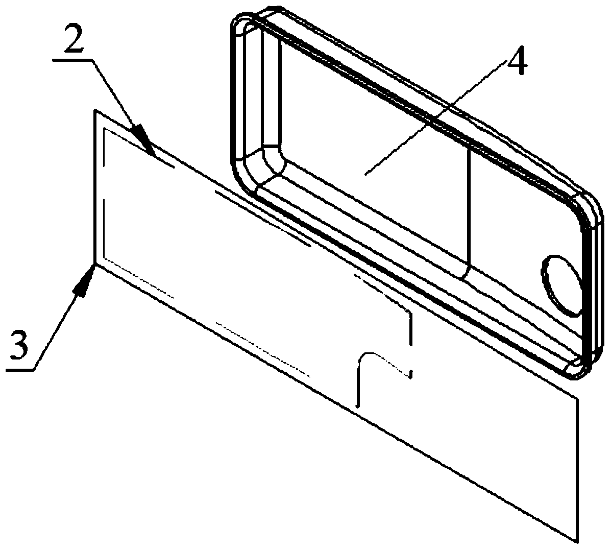
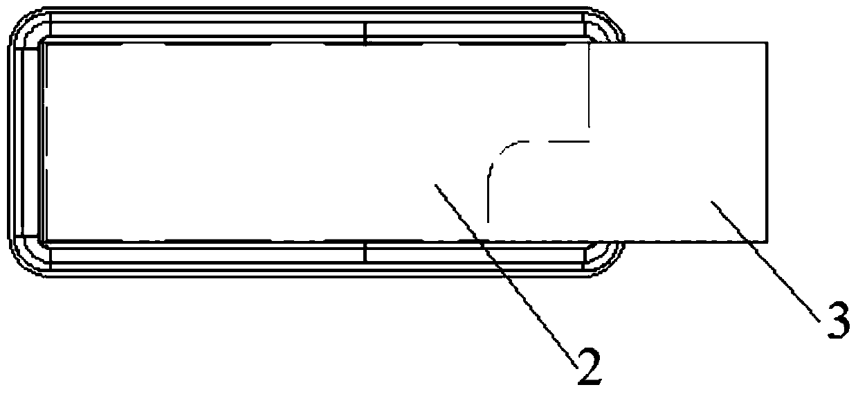
[0030] (1) Die-cut the patch pasted on the negative, so that the patch is die-cut into a set shape, and ensure that the negative is complete, leaving intervals between the patches on the negative, laying a carrier on the surface of the patch, and The carrier is bonded to the surface of all die-cut patches at the same time, and the carrier is die-cut so that a carrier film is formed on the surface of each patch, and the size of the carrier film corresponds to the internal size of the groove of the electronic product , at the same time, the size of the carrier film is larger than the patch size, after the carrier is die-cut as figure 1 As shown, the patch 2 is arranged on the negative sheet 1, and the carrier film 3 is arranged on the surface of the patch 2; the carrier film 3 is a hard film. The patch 2 is a flexible membrane.

[0031] Wherein, the width of the carrier ...


PUM


Abstract

The invention relates to a surface-mounting method in a groove of an electronic product. The method comprises the steps of firstly, performing die cutting on patches pasted on a substrate so that the patches are die-cut into set shapes and the substrate is enabled to be complete, wherein distances are reserved among the patches on the substrate; laying carriers on surfaces of the patches, and simultaneously pasting the carriers on the surfaces of all patches after die cutting; performing die cutting on each carrier so that a carrier film is correspondingly formed on a surface of each patch, and enabling the size of the carrier film to be corresponding to the internal size of the groove of the electronic product, wherein the size of the carrier film is simultaneously larger than the size of the patch; tearing the carrier film with the patch from the substrate, allowing a bonding surface of the patch to face downwards, enabling the carrier film to be aligned to a frame of the internal groove of the electronic product, and pasting the patch and the carrier film in the groove of the electronic product; and taking the carrier film from the surface of the patch, and completing surface mounting in the groove of the electronic product, wherein only the patch is pasted in the groove. Compared with the prior art, the method has the advantages that the production efficiency can be improved, and the rejection ratio of the product is reduced.

Description

technical field [0001] The invention relates to a patching method, in particular to a patching method in a groove of an electronic product. Background technique [0002] With the development of the electronic communication industry, there are more and more specifications and models of electronic products such as mobile phones and tablet computers. In these electronic products, the back cover is generally set as a shield, and the shield is generally not a regular planar shape, but a cover with a groove inside. At the same time, depending on the product, the depth or shape of the groove varies. Similarly, in addition, there are often through holes or some insertion holes for setting the camera on the shielding cover, resulting in an uneven structure in the film-sticking area inside the shielding cover. [0003] These electronic products need to be placed in the groove of the shielding cover before leaving the factory. The general patch is a single-sided adhesive with special ...

Claims


Application Information

Patent Timeline
Patent Type & Authority Patents(China)
IPC IPC(8): H05K13/04
Inventor 邢海杜月华
Owner HANGZHOU HAIZE ELECTRONICS TECH CO LTD
Why Eureka
Try Eureka