Static barrier mixing device for semi-solid-state alloy pulp-making

A semi-solid and barrier technology, applied in the field of static barrier mixing devices for semi-solid alloy pulping, can solve the problems of no temperature control device, narrow temperature range, high equipment cost, etc.

Active Publication Date: 2017-03-15
GUANGDONG YIZUMI PRECISION MACHINERY
View PDF4 Cites 4 Cited by
  • Summary
  • Abstract
  • Description
  • Claims
  • Application Information

AI Technical Summary

Problems solved by technology

[0003] However, there are three common shortcomings in mechanical stirring pulping equipment. The first is that the process of pulping and stirring is exposed to the air environment. During the stirring process, a large amount of air will be stirred in at the same time, so that many pores and air pockets are formed on the product. It affects the mechanical properties and processing properties of die-casting products and reduces the yield of products; the second is that the metal liquid is cooled in the air without a temperature control device. The entire pulping process is greatly affected by the surrounding air temperature, and the alloy forms half The temperature range of the solid state is generally relatively narrow. Stirring in an unstable temperature state makes it difficult to maintain a stable pulping quality; the third is that mechanical stirring requires external power sources and transmission mechanisms (such as motors and transmission pairs) , and the transmission mechanism needs the fixation and support of the auxiliary mechanical mechanism. A complete set of mechanical stirring and pulping equipment is costly and requires an independent control system, which also increases the time and cost of maintenance and maintenance.

Method used


Image

  • Static barrier mixing device for semi-solid-state alloy pulp-making
  • Static barrier mixing device for semi-solid-state alloy pulp-making
  • Static barrier mixing device for semi-solid-state alloy pulp-making

Examples


Embodiment Construction

[0022] The present invention will be further described below in conjunction with the accompanying drawings and embodiments.

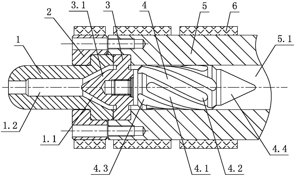
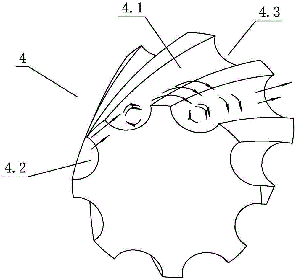
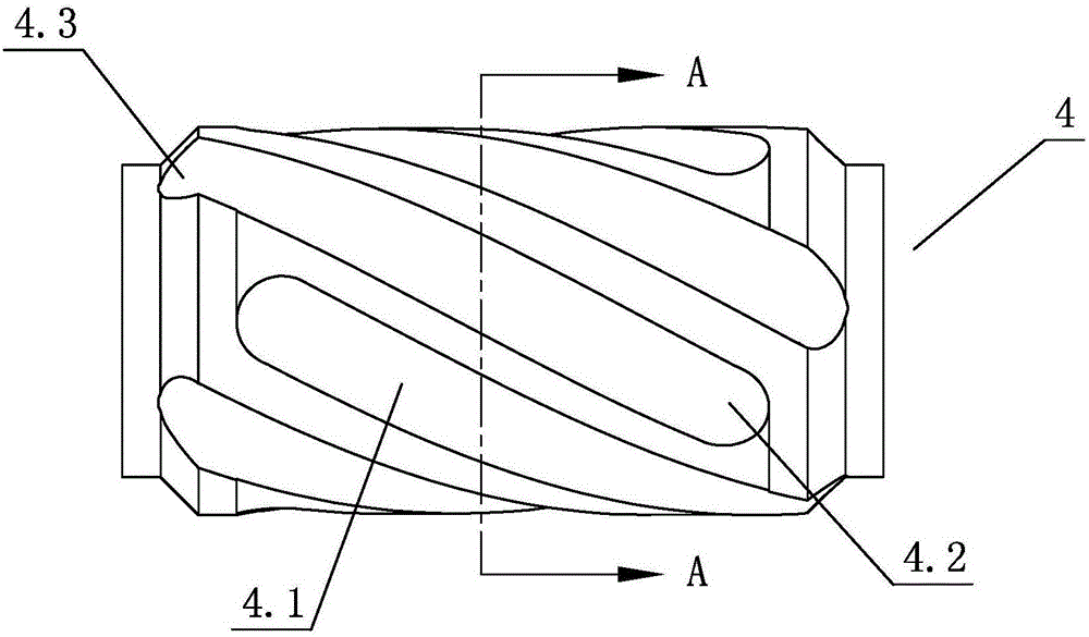
[0023] see Figure 1-Figure 4 , the static barrier mixing device for semi-solid alloy pulping, including a nozzle 1 and a barrel 5, the nozzle 1 is arranged on the barrel 5, a collecting comb plate 3 is arranged between the nozzle 1 and the barrel 5, and the barrel 5 A cavity 5.1 is arranged inside the cavity 5.1, and a barrier mixing head 4 is arranged inside the cavity 5.1. The barrier mixing head 4 is statically arranged in the cavity 5.1, and a plurality of chute 4.1 is spirally arranged on its outer wall.

[0024] Furthermore, the barrier mixing head 4 is cylindrical, the shape of the cavity 5.1 corresponds to the barrier mixing head 4, and the periphery of the barrier mixing head 4 and the inner wall of the cavity 5.1 statically cooperate with each other.

[0025] Furthermore, the outer wall of the barrier mixing head 4 is spirally provided with ...


PUM


Abstract

The invention discloses a static barrier mixing device for semi-solid-state alloy pulp-making. The static barrier mixing device comprises a barrier mixing head, a flow concentrating comb plate, a material barrel, a spray nozzle, a spray nozzle flange and a heater, wherein the barrier mixing head is statically arranged in a cavity; and a plurality of inclined slots are spirally formed in the outer wall of the barrier mixing head. Through the improvement on the structure, the plurality of inclined slots are spirally formed in the outer wall of the screen mixing head, metal melt is pushed to the barrier mixing head by utilizing pressure, and crystal nucleus of the metal melt is refined through the shearing action of the barrier mixing head and the material barrel, so that the semi-solid-state pulp preparation requirements are met. The static barrier mixing device has the characteristics of being simple and reasonable in structure, excellent in performance, quick to assemble, convenient to operate, low in manufacturing cost, easy to produce and realize, safe and reliable, and the like, and is high in practicability.

Description

technical field [0001] The invention relates to a static barrier mixing device for semi-solid alloy pulping. Background technique [0002] Mechanical stirring to produce semi-solid slurry refers to the process of continuously stirring the melt with high-temperature-resistant material rods to produce slurry during the cooling of the metal liquid to the temperature between the two phases. The theoretical basis of this process is: in the strong convective melt caused by stirring, at the beginning of solidification, the grains that grow in the form of dendrites after nucleation are deformed and broken by the secondary dendrite arms, resulting in a large increase in the number of free crystal nuclei. And grow in the form of cells or spheres. Explosive nucleation at the initial stage of solidification makes a sharp increase in the number of crystal nuclei a target, so low-temperature pouring of superalloys with refined grains has become a liquidus semi-solid slurrying process. ...

Claims


Application Information

Patent Timeline
Patent Type & Authority Applications(China)
IPC IPC(8): C22C1/00
CPCC22C1/12
Inventor 隋铁军梁启华陈冲
Owner GUANGDONG YIZUMI PRECISION MACHINERY
Why Eureka
Try Eureka