Pipeline conveying equipment, consumable pressure conveying pipe and manufacturing method thereof

A technology for conveying pipelines and manufacturing methods, which is applied in the manufacture of consumable pressure conveying pipelines, consumable pressure conveying pipelines and pipeline conveying equipment with them, and can solve the problems of inconvenient application of design ideas and methods of pressure vessels, large quality, etc. , to achieve the effect of accurate design ideas and directions

Active Publication Date: 2019-06-25
ZOOMLION HEAVY IND CO LTD
View PDF6 Cites 0 Cited by
  • Summary
  • Abstract
  • Description
  • Claims
  • Application Information

AI Technical Summary

Problems solved by technology

Since the pressure vessel is essentially a quasi-static structure, more attention is paid to its pressure bearing capacity, and it is usually designed to have a larger wall thickness in order to have a higher safety factor, but this leads to a larger mass
Therefore, due to the different performance of the lining (consumable pressure transmission pipelines are usually brittle linings to have wear resistance), there are large differences in working conditions and required safety levels, and the design ideas and methods of pressure vessels are not the same. Not easy to apply to consumable pressure delivery pipelines

Method used

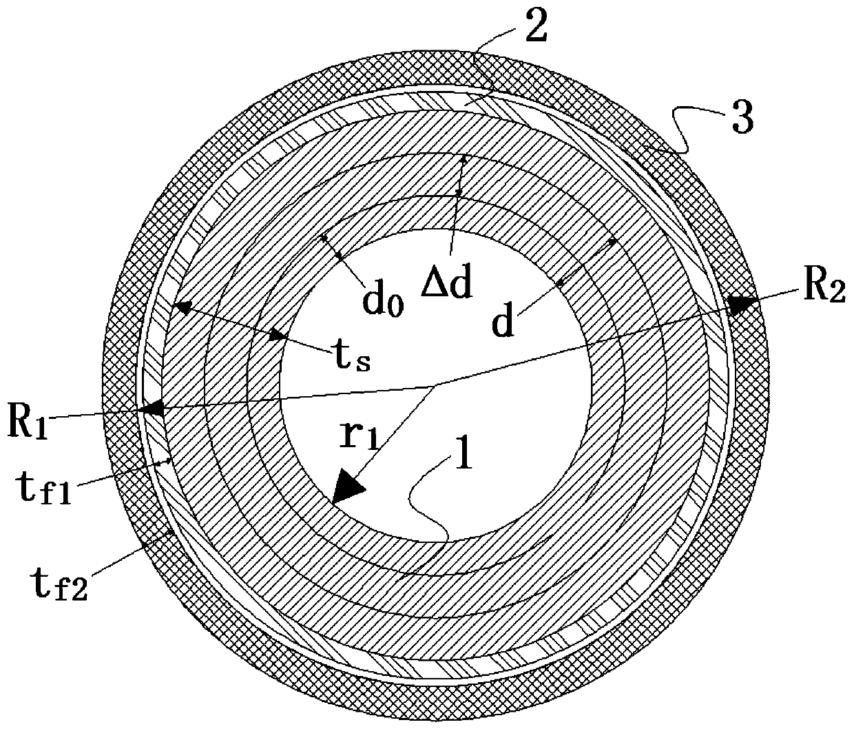
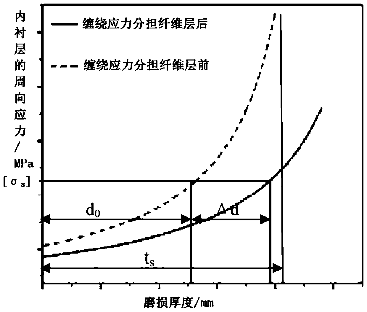

Image

  • Pipeline conveying equipment, consumable pressure conveying pipe and manufacturing method thereof
  • Pipeline conveying equipment, consumable pressure conveying pipe and manufacturing method thereof
  • Pipeline conveying equipment, consumable pressure conveying pipe and manufacturing method thereof

Examples


Embodiment Construction

[0033] The specific embodiments of the present invention will be described in detail below with reference to the accompanying drawings. It should be understood that the specific embodiments described here are only used to illustrate and explain the present invention, and are not used to limit the present invention.

[0034] For ease of understanding, in the following description, a concrete delivery pipe is taken as an example to describe the preferred structure of the present invention for providing a lossy pressure delivery pipeline, and then the key steps for manufacturing the lossy pressure delivery pipeline are described in detail. Personnel can comprehend and implement various technical solutions defined in the appended claims of the present invention from the description of the preferred structure and key steps.

[0035] First refer to figure 1 As shown, the lossy pressure conveying pipe according to a preferred embodiment of the present invention can typically be used as a ...


PUM


Abstract

The invention relates to the field of pipeline conveying equipment, and discloses a pipeline conveying device, a wear type pressure conveying pipeline and a manufacturing method hereof. The wear type pressure conveying pipeline comprises an inside liner (1), and a fiber layer which coils the periphery of the inside liner (1). The manufacturing method comprises the step of coiling a stress sharing fiber layer (2) with first design thickness (tf1) at the periphery of the inside liner (1) according to the extreme target raising value (delta d) of the wear thickness of the inside liner. The wear type pressure conveying pipeline manufactured by the manufacturing method has the advantages that the design thickness of the stress sharing fiber layer (2) is set according to the wear condition exposed to the inside liner (1), so that the design of the stress sharing fiber layer (2) can meet the original arrangement objective, and reasonable and accurate design ideal and direction are provided.

Description

Technical field [0001] The invention relates to the field of pipeline transportation equipment, in particular to a method for manufacturing a lossy pressure transportation pipeline. In addition, the present invention also relates to a lossy pressure conveying pipeline and a pipeline conveying equipment having the same. Background technique [0002] The use of pipelines as a means of transportation for long-distance transportation of liquid, gas or solid slurry is an important material transportation method in industrial production, and it is widely used. Among them, the pipeline as a means of transportation is constantly worn out and Withstand the working internal pressure and are collectively referred to herein as lossy pressure transmission pipelines. Typically, a concrete delivery pump continuously delivers concrete pressurized by the pump body to a predetermined location through a delivery pipe. The delivery pipe used to deliver the concrete here is a common lossy pressure d...

Claims


Application Information

Patent Timeline
Patent Type & Authority Patents(China)
IPC IPC(8): F16L9/16B32B1/08B32B5/02B32B37/02
CPCB32B1/08B32B5/02B32B37/02B32B2307/50B32B2307/554B32B2307/714B32B2597/00F16L9/16
Inventor 刘延斌郭伦文蒋凯歌李飞汪斌
Owner ZOOMLION HEAVY IND CO LTD
Why Eureka
Try Eureka