
Laser working state control method and optical module

A technology of working state and control method, applied in the field of optical communication, can solve the problem that the laser cannot be started effectively, and achieve the effect of avoiding false shutdown

Active Publication Date: 2020-02-14
HISENSE BROADBAND MULTIMEDIA TECH
View PDF6 Cites 0 Cited by
  • Summary
  • Abstract
  • Description
  • Claims
  • Application Information

AI Technical Summary

Problems solved by technology

[0005] In order to solve the problem that the laser may not be able to start effectively when the optical module is powered on in the related art, the present invention provides a method for controlling the working state of the laser and an optical module

Method used


Image

  • Laser working state control method and optical module
  • Laser working state control method and optical module
  • Laser working state control method and optical module

Examples


Embodiment Construction

[0021] In order to make the object, technical solution and advantages of the present invention clearer, the implementation manner of the present invention will be further described in detail below in conjunction with the accompanying drawings.

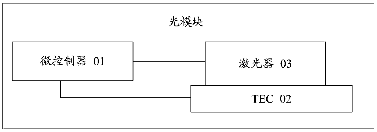
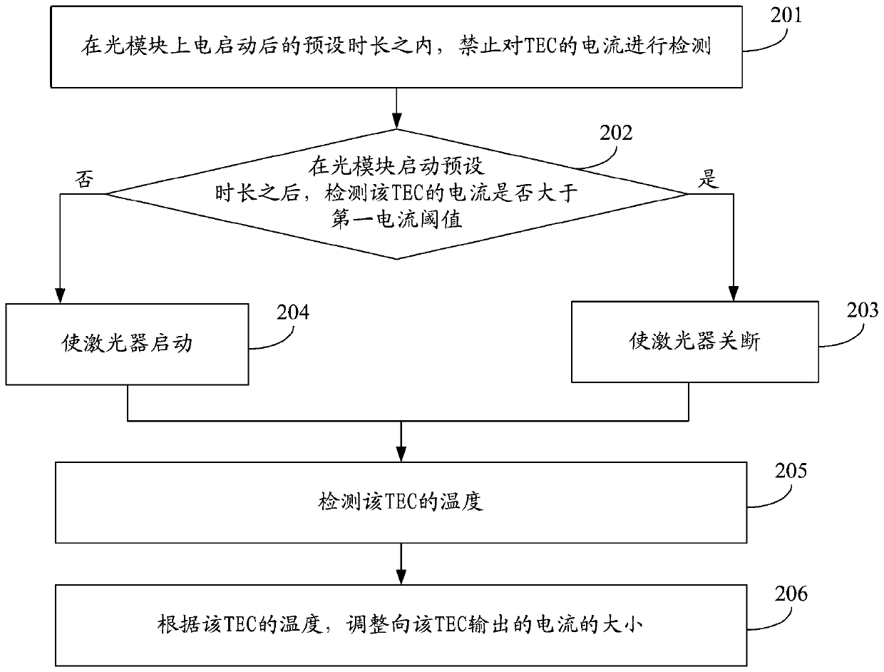
[0022] figure 1 is a flow chart of a method for controlling the working state of a laser provided by an embodiment of the present invention, and the method can be applied to figure 2 In the optical module shown, such as figure 2 As shown, the optical module can include microcontroller 01, TEC 02 and laser 03, refer to figure 1 , the party can include:

[0023] Step 101 , after the optical module is activated for a preset period of time, detect whether the current of the TEC in the optical module is greater than a first current threshold.

[0024] Wherein, starting the optical module may refer to starting each component in the optical module, such as a microcontroller (English: Microcontroller Unit; MCU for short) 01 , TEC 02 and l...


PUM


Abstract

The invention discloses a method for controlling the working state of a laser and an optical module, belonging to the technical field of optical communication. The method is applied to an optical module, and the method includes: after the optical module is started for a preset period of time, detecting whether the current of the TEC in the optical module is greater than a first current threshold; when the current of the TEC is greater than the first current threshold When a current threshold is reached, the laser in the optical module is turned off. Since the microcontroller detects whether the current of the TEC is greater than the first current threshold, the laser is already in a stable working state, and the change of the current of the TEC also tends to be stable. Therefore, the misjudgment caused by the sudden change of the TEC current when the microcontroller detects immediately after power-on and start-up can be avoided, thereby preventing the laser from being erroneously turned off after power-on and start-up.

Description

technical field [0001] The invention relates to the technical field of optical communication, in particular to a method for controlling the working state of a laser and an optical module. Background technique [0002] The laser is the light source device in the optical module, and its working performance and service life are closely related to the working temperature. In general, it is necessary to make the laser work in a stable low temperature environment as much as possible. [0003] In the related art, in order to prevent the working temperature of the laser from being too high and affect the life of the device, the optical module is usually provided with a control circuit for controlling the working temperature and working state of the laser. The control circuit mainly includes: a microcontroller, a semiconductor cooler (English: Thermo Electric Cooler; TEC for short), a TEC driver and a temperature sensor. Among them, the TEC can be attached to the laser to cool the ...

Claims


Application Information

Patent Timeline
Patent Type & Authority Patents(China)
IPC IPC(8): H01S3/131
CPCH01S3/131
Inventor 杨世海张强赵其圣
Owner HISENSE BROADBAND MULTIMEDIA TECH
Learn More