Self-locking valve and system
A self-locking and valve technology, which is applied to valve details, valve devices, devices to prevent accidental or unauthorized actions, etc., to achieve the effect of improving safe operability and ensuring personal safety
- Summary
- Abstract
- Description
- Claims
- Application Information
AI Technical Summary
Problems solved by technology
Method used
Image
Examples
Embodiment 1
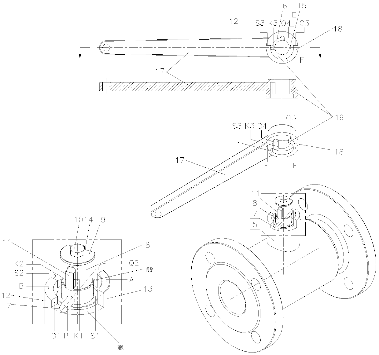
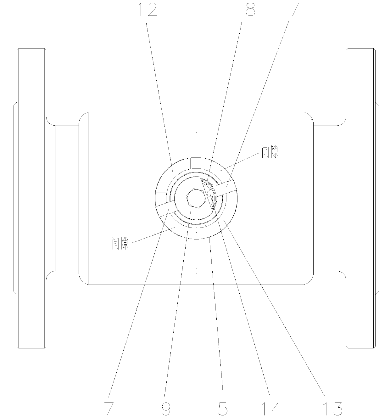
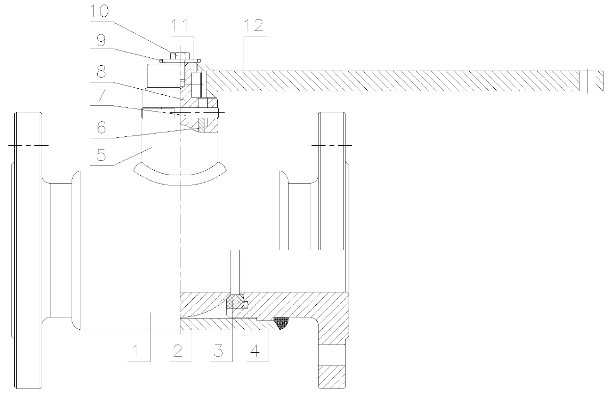
[0030] like Figure 1-Figure 5 As shown, the present invention provides a self-locking valve, including a valve stem 8, the top of the valve stem 8 is connected to a locking part that drives the valve stem to rotate, and the valve stem 8 and the locking part are provided with a self-locking mechanism, and the self-locking The mechanism includes an opening and closing stroke slot 16 provided on the engaging piece, a push block 11 fixed on the valve stem 8 that can run relatively in the opening and closing stroke slot 16, and respectively set on the engaging piece and the valve stem 8. And the card slots that cooperate with each other;
[0031] The self-locking mechanism is a closed position self-locking mechanism. When the valve stem 8 is in the open state, the push block 11 is at the beginning of the opening and closing stroke slot 16; the opening and closing stroke slot 16 is arc-shaped, and it is in line with the valve Rod 8 is concentric.
[0032] The valve stem 8 is shea...
Embodiment 2
[0052] like Figure 1-Figure 5 As shown, the present invention provides a self-locking valve system, which includes the self-locking valve in Embodiment 1 of the above technical solution, and also includes an unlocking key 20, and the unlocking key 20 is engaged with the card slot. The unlocking key is inserted into the card slot for meshing connection; when the valve is opened, the reverse torque T drives the engaging part 19 to rotate, and the unlocking key drives the valve stem 8 to reversely rotate, breaking the idling state of the engaging part 19, and the engaging part 19 Drive the stopper 7 to lock in the second position, and the ball 2 and the housing form an open circuit to open the valve.
[0053] The locking grooves are arranged axially on the rotating surface along the engaging member and the valve stem 8 respectively. Specifically, the card slot is divided into a first groove 14 and a second groove 15 . The first groove 14 is vertically set on the cylindrical su...
Embodiment 3
[0063] Embodiment 1 The technical solution of the self-locking valve can also be applied in the state that the pipeline is normally open and cannot be closed. For example, transport refrigerant to the equipment to cool the equipment. When the delivery of refrigerant is interrupted, the equipment will not be able to dissipate heat sufficiently and be burned out. At this time, this kind of self-locking valve is an open position self-locking valve. The specific application is: the valve is closed at the closed position, and the pipeline is closed at this time; During transportation, the valve is in the open position, it cannot be directly closed again, and the valve is in the open position locked state; that is, the valve can only be opened but not closed, and it cannot be directly closed again when the valve is opened.
[0064] When the valve needs to be closed, use the unlocking key 20 to engage with the card slot; at this time, the valve can be closed.
[0065] The specific ...
PUM
 Abstract
Description
Claims
Application Information
 - R&D Engineer
- R&D Manager
- IP Professional
- Industry Leading Data Capabilities
- Powerful AI technology
- Patent DNA Extraction
Browse by: Latest US Patents, China's latest patents, Technical Efficacy Thesaurus, Application Domain, Technology Topic, Popular Technical Reports.
© 2024 PatSnap. All rights reserved.Legal|Privacy policy|Modern Slavery Act Transparency Statement|Sitemap|About US| Contact US: help@patsnap.com


