Locking device, aircraft and aircraft control method

A technology for locking devices and aircraft, applied in aircraft, unmanned aircraft, transportation and packaging, etc., can solve the problems of easy breakage, complexity and change, difficult to change the position or direction of force on the blade, and achieve Effects of reducing the possibility and avoiding damage

Active Publication Date: 2017-12-15
BOE TECH GRP CO LTD
View PDF5 Cites 6 Cited by
  • Summary
  • Abstract
  • Description
  • Claims
  • Application Information

AI Technical Summary

Problems solved by technology

[0004] On the other hand, in the actual flight process, due to the imperfect flight system of the aircraft itself and the complex and changeable flight conditions, it is inevitable that the flight state of the aircraft will be uncontrollable, which will eventually lead to the aircraft falling
In the process of aircraft falling, the propeller is the most vulnerable part, because the strength of the propeller is usually only able to maintain flight and rotation, and it is easy to break if it is hit
At the same time, since the motors driving the blades mostly use servo motors, when the aircraft falls for some reason, the servo motors are mostly in a non-working state with no signal. At this time, the rotating shaft needs a certain external force to rotate, so the blades are difficult Changing the position or direction of the force, resulting in the impact of the propeller

Method used


Image

  • Locking device, aircraft and aircraft control method
  • Locking device, aircraft and aircraft control method
  • Locking device, aircraft and aircraft control method

Examples


Embodiment Construction

[0036] Embodiments of the present invention are described in detail below, examples of which are shown in the drawings, wherein the same or similar reference numerals designate the same or similar elements or elements having the same or similar functions throughout. The embodiments described below by referring to the figures are exemplary only for explaining the present invention and should not be construed as limiting the present invention.

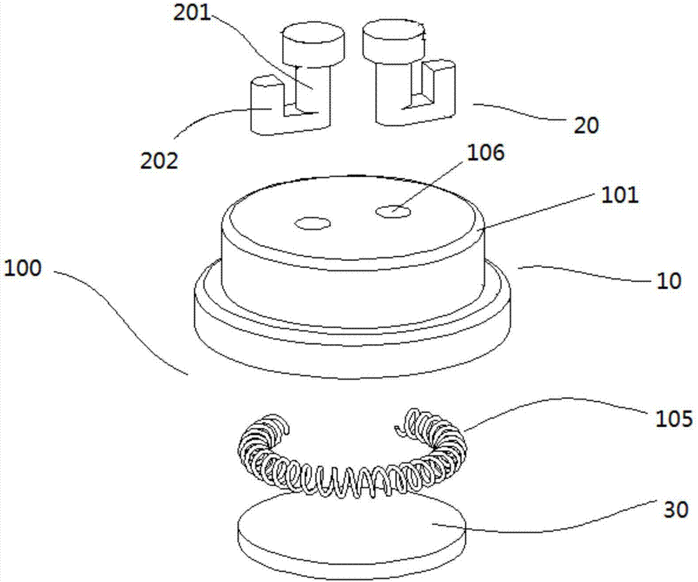
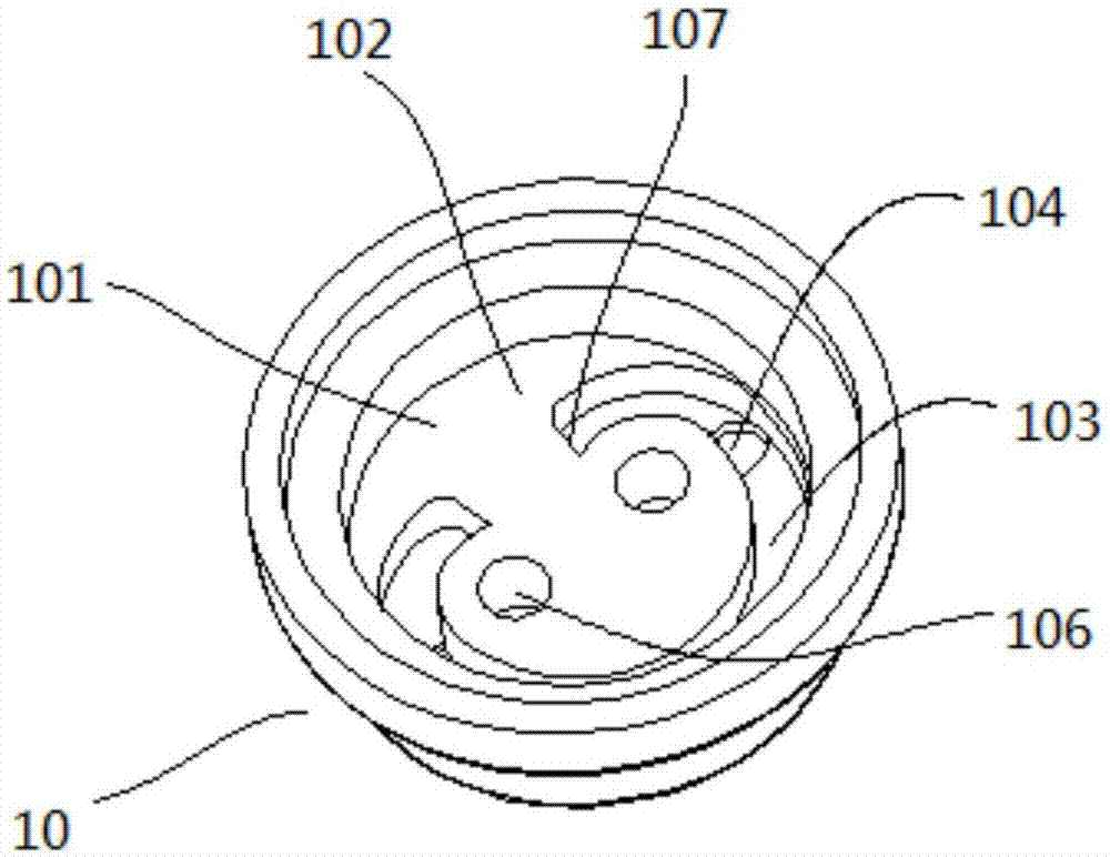
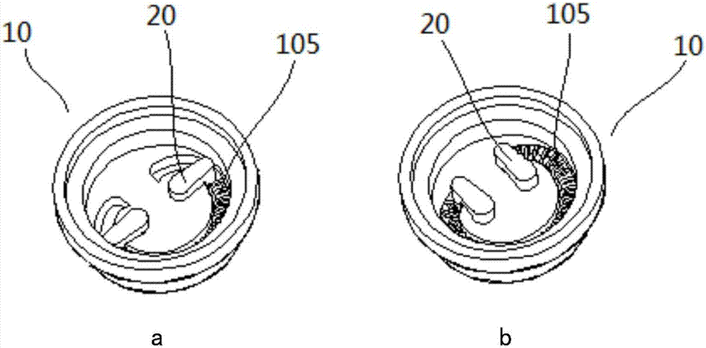
[0037] see figure 1 , figure 2 and image 3 , the locking device 100 of the present invention includes a base 10 and a limiting structure 20 . Specifically, the interior of the base 10 is hollow to form an accommodating space 102, one end of which is fixed with a boss 101, and the side of the boss 101 close to the interior of the base 10, that is, the inner side, is provided with a limiting track 103, so that A limiting slot 104 is provided in the limiting track 103 . The limiting structure 20 includes a rotating guide post 201 and a ...


PUM


Abstract

The invention provides a locking device which comprises a base and a limiting structure. A containing space is formed in the hollow portion of the interior of the base, and one end of the containing space is fixedly provided with a boss; a limiting rail is formed in the inner side surface of the boss, and a limiting groove is formed in the limiting rail; the limiting structure comprises a rotary guide pillar and a limiting part, and the rotary guide pillar is rotatably inserted in the boss and can synchronously drive the limiting part to move close to or away from the boss under the effect of external force so that the limiting part can be clamped into or break away from the limiting groove; and an elastic pushing and pressing piece with one end abutting against the limiting part to apply driving force to the limiting part is arranged in the limiting rail; and after the limiting part breaks away from the limiting groove, the limiting part can be moved to a certain position to be fixed after pushing of the elastic pushing and pressing piece, so that the locking function is achieved. Correspondingly, the invention provides an aircraft, the aircraft applies the locking device, a propeller and wings can be effectively prevented from colliding with the outside.

Description

technical field [0001] The invention relates to the technical fields of locking structure, aircraft and intelligent control, in particular to a locking device and an aircraft, and also to an aircraft control method. Background technique [0002] The use of aircraft is becoming more and more popular. Due to its simple structure and relatively low price, its application scenarios are constantly expanding, and it can be applied to fields such as aerial photography, monitoring and rescue. [0003] Commonly used aircraft will use the corresponding system to control its flight, such as using a hand-held remote control or a pre-set program, by changing the speed of the motors in the four wings of the aircraft to change the force direction of the aircraft to achieve flight, follow, Obstacle avoidance and other functions. Although the structure and principle of the aircraft are relatively simple, in order to realize the long battery life of the small aircraft, the entire fuselage mu...

Claims


Application Information

Patent Timeline
Patent Type & Authority Applications(China)
IPC IPC(8): B64C39/02B64C27/50B64C27/14
CPCB64C27/14B64C27/50B64C39/02B64U10/13B64U30/20B64U50/19
Inventor 王子锋任妍曹磊
Owner BOE TECH GRP CO LTD
Why Eureka
Try Eureka