Wall-through casing pipe flexible waterproof sealing structure and construction method

A wall-piercing sleeve, flexible waterproof technology, applied in the direction of pipes, pipes/pipe joints/pipe fittings, mechanical equipment, etc., can solve the problems of unbalanced force on support points, increased maintenance costs, and difficult processing, etc., to achieve accelerated The effect of large assembly clearance space, prolonging service life and improving connection strength

Pending Publication Date: 2020-04-10
BEIJING TRIUMPH INT ENG +1
View PDF0 Cites 8 Cited by
  • Summary
  • Abstract
  • Description
  • Claims
  • Application Information

AI Technical Summary

Problems solved by technology

[0003] (1) if Figure 1A As shown, the sealing methods and sealing materials used by the first and second sealing components of this structure are different, so that the support points on both sides of the medium pipe 1 inside the wall sleeve 2 are unbalanced, and the rigid sealing material cannot Absorb reasonable deformation displacement and working vibration of medium pipeline, which are more vulnerable to damage and affect the sealing structure effect
[0004] (2) if Figure 1B As shown, the wing ring plates 23 at both ends of the wall-piercing sleeve 2 protrude from the wall 01. This arrangement is inconvenient for formwork support in the construction process, and the wall-piercing sleeve 2 cannot be integrated with the structure of the wall 01 as a whole. The steel bars are effectively connected and fixed, because the wing ring plates 23 at both ends of the wall casing 2 cannot be tightly fixed with the concrete of the wall 01, which affects the connection strength between the wall casing 2 and the wall 01 as a whole
It is difficult to guarantee the waterproof and sealing function under the condition of high groundwater level and high osmotic pressure only by the middle wing ring plate 22
[0005] (4) if Figure 1D As shown, the first sealing assembly between the medium pipeline 1 and the wall casing 2 at the upstream surface of the wall 01 is sealed with a rigid sealing paste 36. When the wall 01 or the medium pipeline 2 is normally displaced and deformed, After the rigid sealing material is subjected to the interaction between the wall casing 2 and the medium pipe 1, the destructive structural gaps generated make the sealing component useless. Watertight sealing function under high pressure
[0006] (5) if Figure 1B As shown, the existing inner retaining ring 24 is arranged inside the wall bushing 2, and the two sides of the inner retaining ring 24 are fully welded with the inner side of the wall bushing 2, when the wall bushing 2 When the pipe diameter is small, the processing is difficult, and it is even impossible to weld on the inside. If the outside is welded, it will directly affect the deformation space of the flexible sealing material and its use effect; when the first sealing component fails, because the two welds are fixed on The inner retaining ring 24 of the casing is blocked and cannot be repaired from the back surface. The damaged first rigid sealing material can only be excavated from the outside of the building wall to replace the sealing material. During the repair process, the outer protective wall will inevitably be The waterproof structure and thermal insulation structure on the outside of the body are damaged, which increases the difficulty and cost of maintenance
[0007] (6) The existing first rigid sealing material is set on the outer facing water surface of wall 01 (see Figure 1D ) failed to play the role of resisting shock waves in wartime stipulated in the code for the design of civil air defense basements, and the overall strength requirements after the wall was opened
[0008] (7) if Figure 1C As shown, in the existing L-shaped flange gland 35 of the second flexible sealing structure, during the pre-tightening construction process, the pre-tightening force of the bolt group acting on the L-shaped flange gland 35 acts on the sealing ring, and There is an assembly pre-tightening space between the L-shaped flange gland 35 and the end wing ring plate 23 of the wall casing 2 to adjust the pre-tightening amount of the sealing ring. During the long-term working vibration of the medium pipeline 1, the bolt group is easy to loosen
If the L-shaped flange cover 35 and the end wing ring plate 23 of the wall bushing 2 are directly locked and locked, although the fastening and self-locking function of the bolt group can be realized, the L-shaped flange cover 35 and the There is a lack of assembly pre-tightening space between the end wing ring plates 23 of the wall bushing 2, and it is impossible to control the reasonable pre-tightening force and sealing deformation of the sealing ring, thus losing the flexible sealing effect

Method used


Image

  • Wall-through casing pipe flexible waterproof sealing structure and construction method
  • Wall-through casing pipe flexible waterproof sealing structure and construction method
  • Wall-through casing pipe flexible waterproof sealing structure and construction method

Examples


Embodiment 1

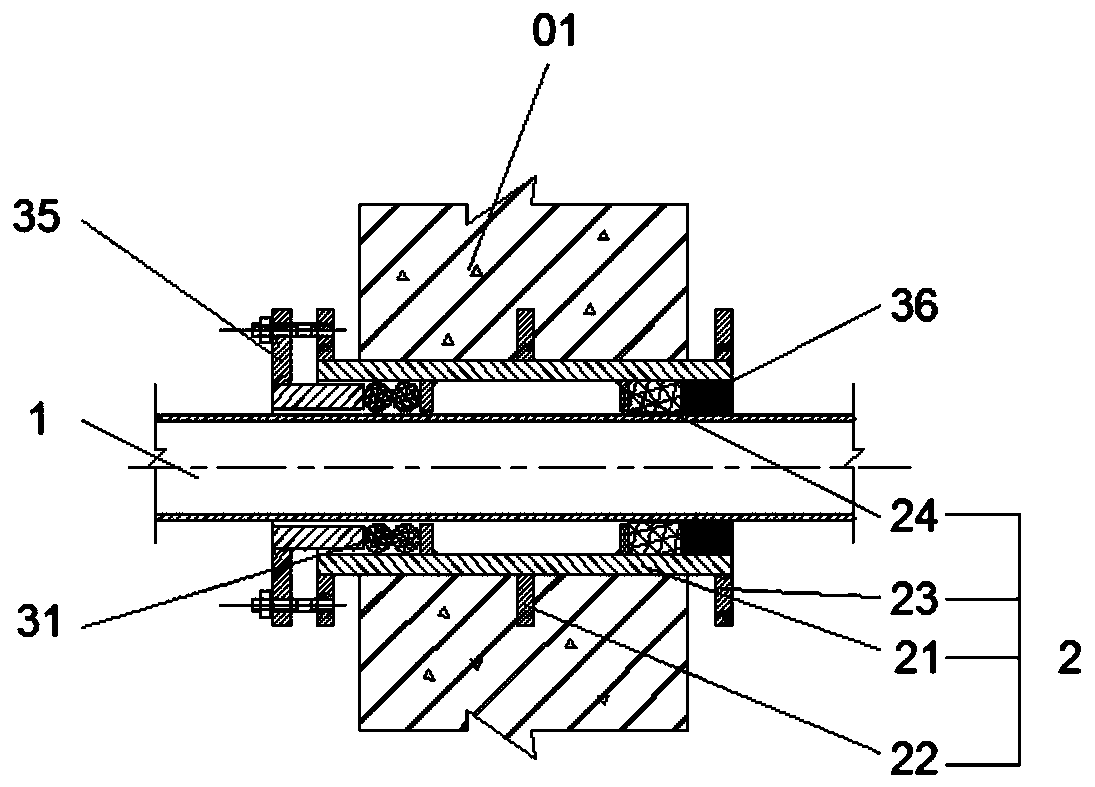
[0054] Figure 2A In the first embodiment shown, the flexible waterproof sealing structure of the wall-piercing sleeve is used to seal the medium pipeline 1 set in the wall 01, including the wall-piercing sleeve 2 and the sealing assembly 3, and the medium pipeline 1 is sheathed in the In the wall bushing 2, the sealing assembly 3 is arranged between the wall bushing 2 and the medium pipeline 1, wherein:

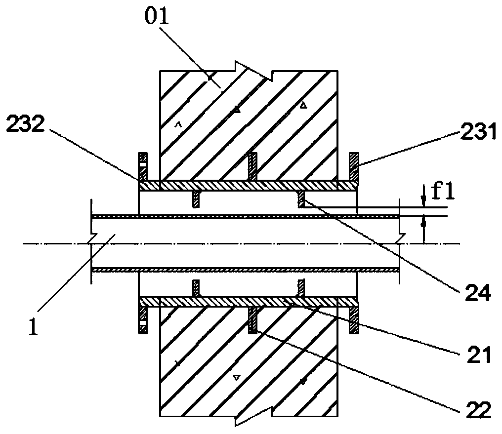
[0055] Existing wall bushing structures such as Figure 1B As shown, there are two inner retaining rings 24 welded inside the pipe body of the wall bushing. The manufacturing process of the structure of this part is complicated. When the pipe diameter of the wall bushing is small, the inner side of the inner retaining ring cannot be welded. Processing, in this structure, the installation gap of the medium pipeline 1 is f1, and the construction and assembly are more difficult. refer to Figure 2B , in this embodiment, the inner retaining ring of the wall bushing 2 is chang...

Embodiment 2

[0075] In this embodiment, the second embodiment of the flexible waterproof sealing structure of the wall casing is as follows: image 3 As shown, the structure is the same as the basic structure of Embodiment 1, and is a reinforced type of Embodiment 1. The difference is that the sealing assembly 3 at least includes flexible sealing assemblies at both ends that are balancedly arranged (the first sealing assembly and the second sealing assembly). sealing assembly) and the flexible sealing assembly (the third sealing assembly) in the middle. Specifically, the sealing assembly 3 is composed of three precompression retaining rings 32 (namely, the axial precompression retaining ring 331 on the upstream surface, the axial precompression retaining ring 332 on the neutral plane and the axial precompression retaining ring 333 on the backwater surface), Three sets of sealing rings 31 separated by three pre-compression retaining rings 32 (namely, the sealing ring 311 on the upstream sur...


PUM


Abstract

The invention provides a wall-through casing pipe flexible waterproof sealing structure and a construction method. The structure comprises a wall-through casing pipe pre-embedded in a wall, a medium pipeline sleeved in the wall-through casing pipe and a sealing assembly arranged between the wall-through casing pipe and the medium pipeline, wherein a middle wing ring plate and an end wing ring plate are arranged on the outer wall of a pipe body of the wall-through casing pipe; the sealing assembly is s flexible sealing structure formed by a plurality of groups of sealing rings which are arranged in the wall-through casing pipe, spaced by non-fixed pre-pressing baffle rings and fastened by end baffles. According to the wall-through casing pipe flexible waterproof sealing structure, the sealing assembly adopts the flexible sealing structure with pre-tightening force, so that the stress of the medium pipe is balanced; the sealing rings are partitioned into a plurality of groups by the non-fixed pre-pressing baffle rings, and the sealing rings are in a pre-tightened deformation state under the action of the end baffles; the positions of two end wing ring plates of the wall-through casing pipe are adjusted, so that the end wing ring plates are embedded into the wall to form a mechanical labyrinth type sealing structure; and the underground waterproof sealing effect under the condition with high water level and high seepage pressure can be met.

Description

technical field [0001] The invention belongs to the professional technical field of water supply and drainage in industrial buildings, civil buildings, and municipal buildings, and relates to a waterproof sealing technology when a medium pipeline passes through a wall of an outer protective structure, in particular to a flexible waterproof sealing structure and a construction method of a wall-through casing . Background technique [0002] At present, in the water supply and drainage majors of industrial buildings, civil buildings, and municipal engineering, when the medium pipeline is buried in the groundwater level and passes through the outer protective structure walls of buildings, structures, etc., the national standard Atlas 02S404 flexible waterproof sleeve type B is usually used. The waterproof and sealing structure of the wall-piercing casing is shown to achieve the predetermined waterproof sealing effect. For the on-site environment accompanied by the settlement def...

Claims


Application Information

Patent Timeline
Patent Type & Authority Applications(China)
IPC IPC(8): F16L5/10
CPCF16L5/10
Inventor 张莹马明亮魏文荣武力姚俊李英任宇霞张树伟王安然
Owner BEIJING TRIUMPH INT ENG
Why Eureka
Try Eureka