A linear constant current LED drive circuit and method compatible with thyristor dimmers
An LED driver and dimmer technology, which is applied in the direction of electric lamp circuit layout, light source, electric light source, etc., can solve the problems of LED flicker, control failure of thyristor dimmer, random occurrence, etc., to improve compatibility problems and avoid possible The effect of thyristor false turn-off phenomenon
- Summary
- Abstract
- Description
- Claims
- Application Information
AI Technical Summary
Problems solved by technology
Method used
Image
Examples
Embodiment 1
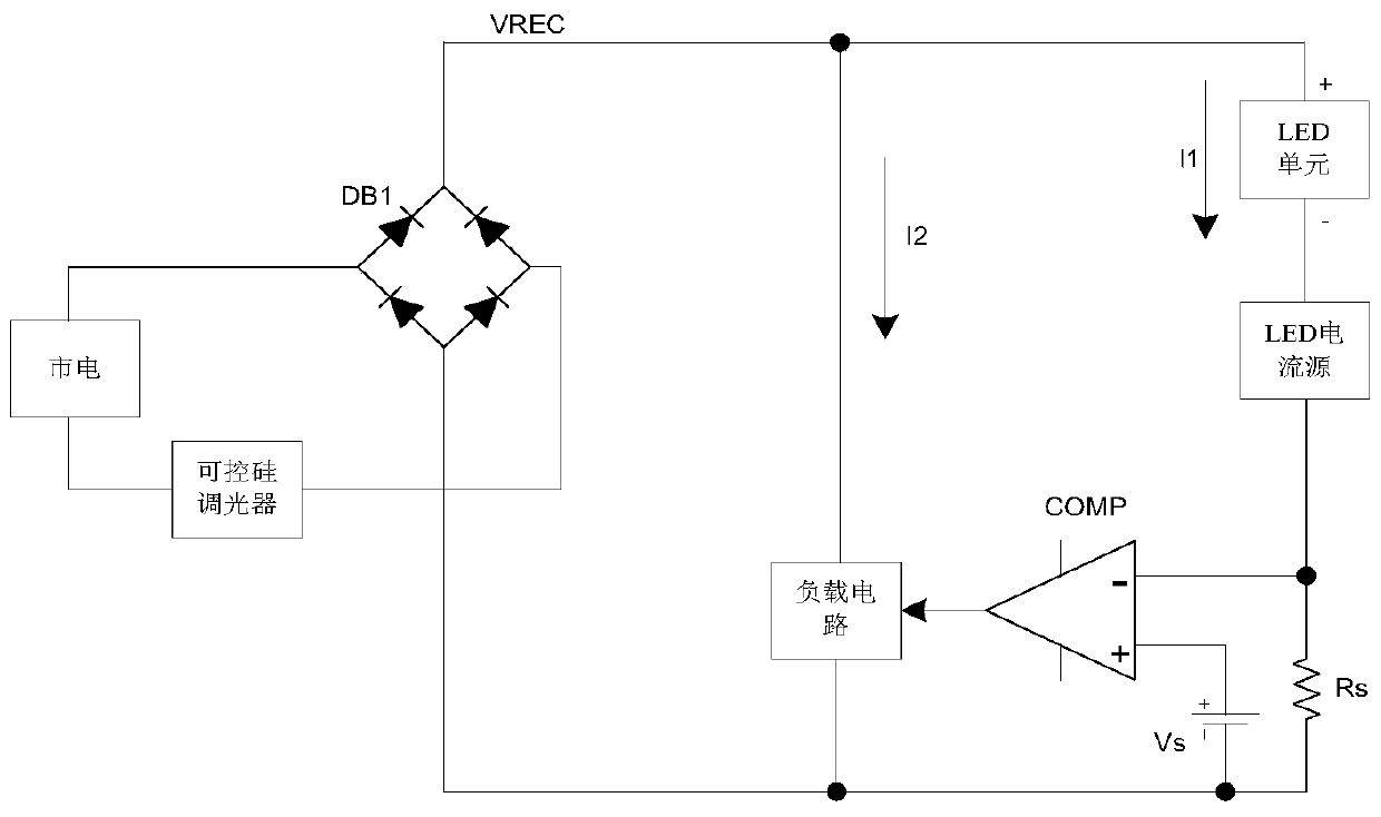
[0040] like image 3 As shown, an LED drive circuit compatible with a thyristor dimmer is powered by mains, and the thyristor dimmer is connected in series to the mains, including a rectifier bridge DB, an LED unit and a combined current source. A combined current source consists of three terminals. The positive pole of the LED unit is connected to the positive pole of the output of the rectifier bridge, the negative pole is connected to the third terminal of the combined current source, the first terminal of the combined current source is connected to the positive pole of the rectifier bridge, and the second terminal is connected to the negative pole of the rectifier bridge.
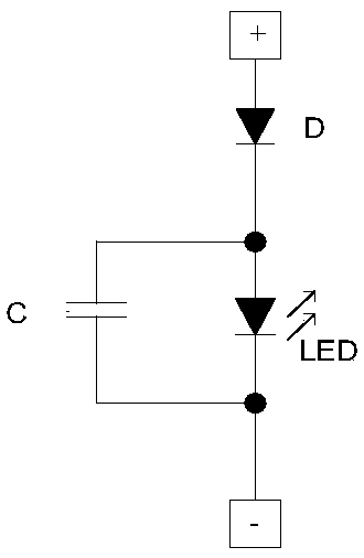
[0041] like Figure 1a As shown, the LED unit includes at least one set of LEDs, an energy storage capacitor and a diode. The energy storage capacitor is connected in parallel to both ends of the LED, the cathode of the diode is connected to the anode of the LED, the anode of the diode is used as the ...
Embodiment 2
[0063] In the second embodiment, except that the circuit structure of the dynamic current source in the combined current source is different from that of the first embodiment, other circuit structures and working principles are the same, and will not be described again.
[0064] like Figure 4 As shown, the combined current source in this embodiment also includes an LED current source, a dynamic current source, a current detection circuit and a current detection resistor, and the specific structure is as follows:
[0065] like Figure 7 As shown, the current detection circuit includes a comparator COMP1-2, a first reference signal V1-2 and a switch S1-2. The LED current source includes a second transistor Q2-2, a second operational amplifier EA2-2 and a second reference signal V2-2. The LED current source and the detection resistor Rn-2 limit the current value of the third terminal of the combined current source. . The dynamic current source includes a third transistor Q3-...
PUM
 Abstract
Description
Claims
Application Information
 - R&D
- Intellectual Property
- Life Sciences
- Materials
- Tech Scout
- Unparalleled Data Quality
- Higher Quality Content
- 60% Fewer Hallucinations
Browse by: Latest US Patents, China's latest patents, Technical Efficacy Thesaurus, Application Domain, Technology Topic, Popular Technical Reports.
© 2025 PatSnap. All rights reserved.Legal|Privacy policy|Modern Slavery Act Transparency Statement|Sitemap|About US| Contact US: help@patsnap.com


