
Heavy-load hydraulic lifting device

A lifting device, hydraulic technology, used in the direction of tilting load-bearing vehicles, etc.

Inactive Publication Date: 2014-04-16
FAW JIEFANG LIUZHOU SPECIAL AUTOMOBILE
View PDF7 Cites 0 Cited by
  • Summary
  • Abstract
  • Description
  • Claims
  • Application Information

AI Technical Summary

Problems solved by technology

[0003] In order to solve the technical problem that the current automobile cannot control the slope of the automobile compartment due to the lack of stop structure facilities of the hydraulic lifting device, the present invention provides a heavy-duty hydraulic lifting device

Method used


Image

  • Heavy-load hydraulic lifting device

Examples


Embodiment Construction

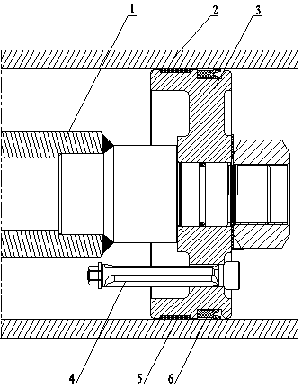
[0016] like figure 1 Shown is the preferred embodiment of the heavy-duty hydraulic lifting device of the present invention.

[0017] The heavy-duty hydraulic lifting device includes a push rod 1, a cylinder 2 and a piston 3, and also includes a limit rod 4, which is fixedly connected with the piston 3, and moves along with the piston 3 along the Cylinder 2 slides axially.

[0018] In this embodiment, the heavy-duty hydraulic lifting device further includes a guide belt 5 installed between the cylinder 2 and the piston 3 .

[0019] In this embodiment, the heavy-duty hydraulic lifting device further includes a sealing ring 6, which is installed between the cylinder 2 and the piston 3, and the cross section of the sealing ring 6 is "Y". "type.

[0020] Apparently, the above-mentioned embodiments are only examples for clear description, rather than limiting the implementation. For those of ordinary skill in the art, other changes or changes in different forms can be made on t...


PUM


Abstract

A heavy-load hydraulic lifting device comprises a push rod (1), a cylinder tube (2) and a piston (3) and is characterized by further comprising a limit rod (4). The limit rod (4) is fixedly connected with the piston (3). The piston (3) axially slides along the cylinder tube (2). The heavy-load hydraulic lifting device has the advantages that by the added limit rod (4), the inclination of an automobile carriage can be controlled during lifting, and automobile carriage lifting safety is increased while heavy load is increased.

Description

technical field [0001] The invention relates to a lifting device, in particular to a heavy-duty hydraulic lifting device. Background technique [0002] At present, the heavy-duty hydraulic lifting devices on automobiles do not have intermediate stop structure facilities. Therefore, during the lifting process, the inclination of the automobile compartment cannot be controlled, which is not only a waste of time, but also very dangerous under heavy load conditions. Contents of the invention [0003] In order to solve the technical problem that the current automobile cannot control the inclination of the car compartment because the hydraulic lifting device has no stop structure facilities, the invention provides a heavy-duty hydraulic lifting device. [0004] The technical scheme that the present invention adopts is as follows: [0005] A heavy-duty hydraulic lifting device includes a push rod, a cylinder, and a piston, and also includes a limit rod, which is fixedly connect...

Claims


Application Information

Patent Timeline
Patent Type & Authority Applications(China)
IPC IPC(8): B60P1/16
Inventor 庞胜陈文潮梁承欢刘振强
Owner FAW JIEFANG LIUZHOU SPECIAL AUTOMOBILE
Learn More