A rolling system and its working method

A technology of rolling and rolling machine, applied in grain processing and other directions, can solve the problem of difficulty in adjusting the inclination of the slanting plate, and achieve the effects of improving the connection strength, increasing the connection area and high adjustment accuracy

Active Publication Date: 2022-07-15
MAANSHAN GELIN MINING & METALLURGY ENVIRONMENTAL PROTECTION EQUIP
View PDF8 Cites 0 Cited by
  • Summary
  • Abstract
  • Description
  • Claims
  • Application Information

AI Technical Summary

Problems solved by technology

[0007] Aiming at the problem that it is difficult to adjust the inclination of the slanting plate when the existing feeding device of the roller press adopts the slanting plate to control the feeding opening, the present invention provides a rolling system that can conveniently and quickly adjust the rolling machine The slope of the inclined plate is convenient to adjust according to different types of materials when the roller press is working, so as to improve the working effect of the roller press

Method used


Image

  • A rolling system and its working method
  • A rolling system and its working method
  • A rolling system and its working method

Examples


Embodiment 1

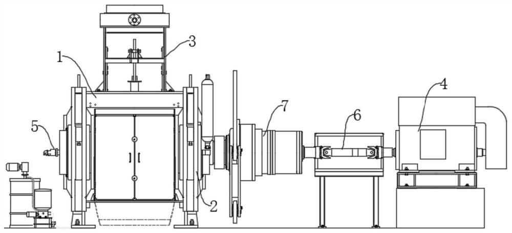
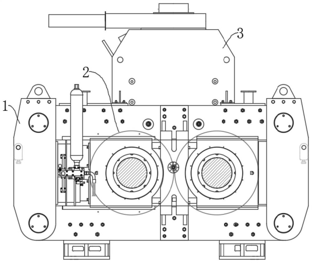
[0039]like figure 1 and figure 2 As shown, a rolling system is used for grinding materials to smaller particle size, which includes a rolling machine frame 1, a motor 4, a reducer 7 and a cooling device 5, and the lower part of the rolling machine frame 1 A squeezing roller 2 is provided, and a feeding device 3 is provided on the upper part. The specific structure and working principle of the system are described in detail below.

[0040] Among them, the motor 4 and the reducer 7 are the power devices that drive the squeezing roller 2 to rotate. The lower part of the motor 4 is provided with a motor seat, and the motor 4 is fixedly arranged on the motor seat. The output shaft of the motor 4 is drivingly connected to one of the output shafts of the reducer 7 through the transmission shaft 6, and the other output shaft of the reducer 7 is connected to the roller of the squeeze roller 2 in a drive connection to control the rotation of the squeeze roller 2. The way of the tran...

Embodiment 2

[0052] A kind of rolling system working method, adopts a kind of rolling system of embodiment 1, and its process is as follows:

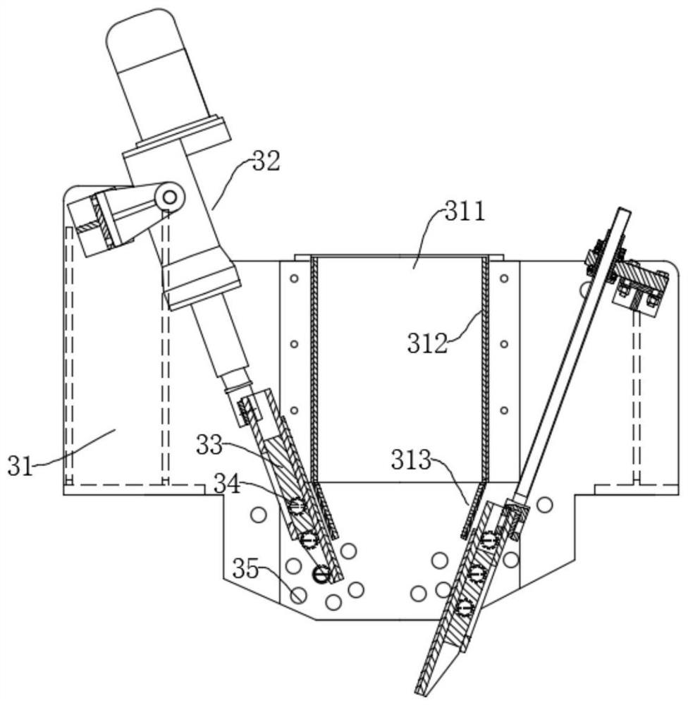
[0053] The telescopic mechanism 32 retracts the inclined insert plate 33, and then, according to the set inclination, the guide rollers 34 are installed on the corresponding pair of installation holes 35, and then the telescopic mechanism 32 works to make the upper plate 331 and the lower plate of the inclined insert plate 33. 332 passes through the mounted guide rollers 34. After that, the motor 4 is started, and the material is poured from the feeding port 311 of the feeding device 3 , and the material falls between the extrusion rollers 2 from the feeding device 3 .

[0054] In the working method of the rolling system in this embodiment, by using the rolling system in Embodiment 1, the telescopic mechanism 32 only needs to be hingedly arranged with the feeding frame 31, and the oblique plate 33 can be adjusted without disassembling and installing...


PUM


Abstract

The invention discloses a rolling system and a working method thereof, belonging to the field of rolling equipment. The system includes a roller press frame and a motor, the lower part of the roller press frame is provided with a squeezing roller, and the upper part is provided with a feeding device, the squeezing roller is drivingly connected with the output shaft of the motor, and the feeding The device includes a feeding frame, a telescopic mechanism and an oblique inserting plate; the inclined inserting plate is fixedly connected with the telescopic part of the telescopic mechanism, including fixedly connected upper and lower plates, and the lower part of the feeding frame is along the direction of the extrusion roller. A guide roller is provided in the axial direction; the telescopic mechanism is hingedly connected with the upper part of the feeding frame, and the guide roller is located in the cavity between the upper plate and the lower plate, which can easily and quickly adjust the slanting plate of the roller press. The inclination is convenient for the roller press to be adjusted according to different types of materials when it is working, and the working effect of the roller press is improved. The method adopts the above-mentioned rolling system, which can conveniently control the inclination of the slanted insert plate and adapt to different kinds of materials.

Description

technical field [0001] The invention belongs to the technical field of rolling equipment, and more particularly, relates to a rolling system and a working method thereof. Background technique [0002] The roller press is designed according to the principle of material bed grinding, and its main features are: high pressure, full speed, full material, and material bed grinding. The roller press consists of two squeeze rollers that rotate synchronously in opposite directions, one is a fixed roller and the other is a movable roller. The granular material is fed from the top of the two rollers, and is continuously brought between the rollers by the squeezing roller. After being subjected to high pressure, it becomes a dense cake and is discharged from the bottom of the machine. The discharged cake contains a certain proportion of fine-grained products. In the interior of the non-finished particles, a large number of cracks are generated, which improves the grindability of the m...

Claims


Application Information

Patent Timeline
Patent Type & Authority Patents(China)
IPC IPC(8): B02C4/02B02C4/28B02C4/44B02C23/02
CPCB02C4/02B02C4/286B02C4/44
Inventor 刘兵汪再青洪伏珍李书会尹和平于江
Owner MAANSHAN GELIN MINING & METALLURGY ENVIRONMENTAL PROTECTION EQUIP
Why Eureka
Try Eureka