Swinging strip steel guiding conveying device

A conveying device and guiding device technology, which is applied in the field of conveying and guiding devices to the coiler, can solve the problems of disrupting the production rhythm, complicated maintenance, and high energy consumption, so as to reduce waste, avoid fire accidents, and save investment little effect

Inactive Publication Date: 2011-01-19
MAANSHAN IRON & STEEL CO LTD
View PDF0 Cites 0 Cited by
  • Summary
  • Abstract
  • Description
  • Claims
  • Application Information

AI Technical Summary

Problems solved by technology

Due to the thinner head of the strip steel and the upturning caused by the process, the head of the strip steel is easy and often directly drills into the gap, resulting in the fault of stacking steel; On the turning surface, when the head of the strip steel touches any one of the turning surfaces, there may be a failure of folding and stacking steel, which will cause the entire production line to stop production, disrupt the production rhythm, reduce the operating rate, increase waste products, consume more energy, and increase production costs; The mechanism is complicated, there are many faults, the maintenance is complicated, and the consumption of spare parts is high; the switching mechanism uses hydraulic cylinders and fire accidents will occur

Method used


Image

  • Swinging strip steel guiding conveying device
  • Swinging strip steel guiding conveying device
  • Swinging strip steel guiding conveying device

Examples


Embodiment Construction

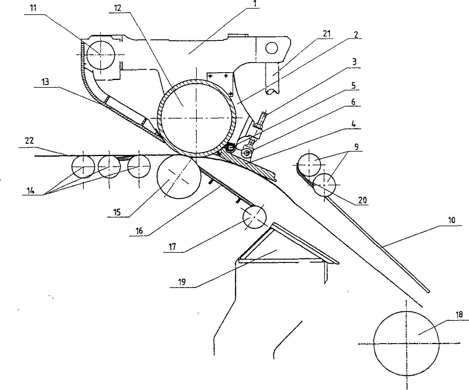
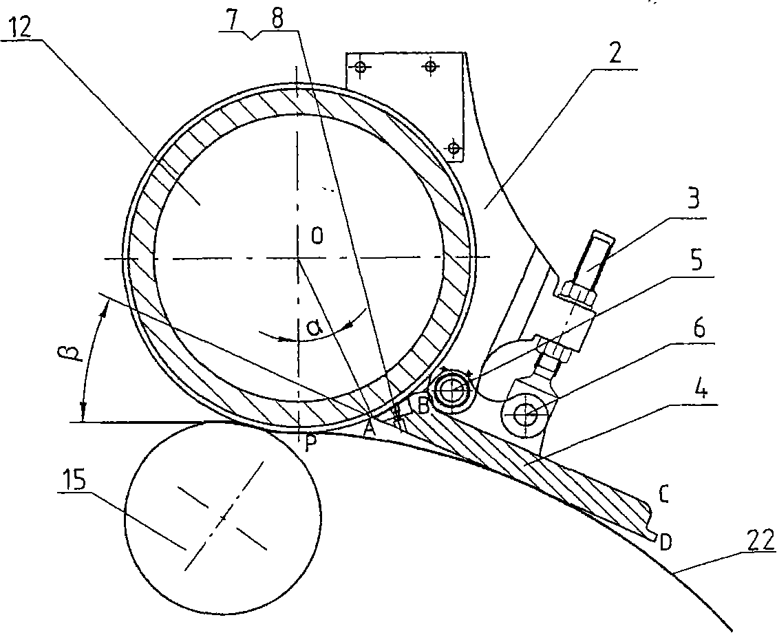
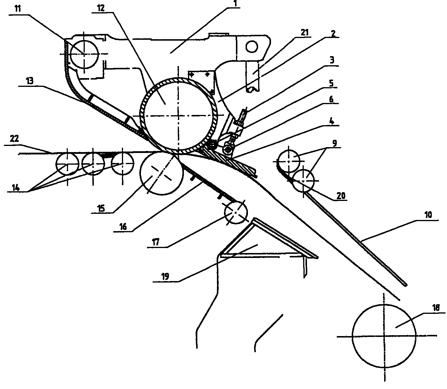
[0015] figure 1 It is a cross-sectional view of the device of the present invention. In the figure, the strip steel 22 is single-linear, the upper pinch roller 12, the lower pinch roller 15, the switch roller 9, the frame roller 14, and the lower switch roller 17 that the strip passes through are all represented by circles, and the guide plate 4 is represented by ABCD The enclosed figure shows that the top of the guide plate 4 is connected to the plane by a cylindrical concave arc surface 7, represented by arcs AB and BC, and the bottom of the guide plate 4 is a plane, represented by AD. The biting point between the strip steel 22 and the upper pinch roller 12 is represented by the tangent point P between the line segment and the circle, and the gap between the front end of the guide plate 4 and the upper pinch roller 12 is represented by A, then ∠AOP is the back-shift angle α , the angle between the bottom surface AD ​​of the guide plate 4 and the rolling line is represented...


PUM


Abstract

The invention relates to a rotary guidance and transport device for band steel, belonging to the technical field of guidance and transport device for flexible workpiece, in particular to the device for guiding and transporting the band steel made by continuous casting and continuous rolling to a thin slab to a coiler. The device is characterized in that: an upper pinch roll is fixedly arranged ona swing arm, while the swing arm and a lower pinch roll are fixedly arranged in a housing window; the rotary guidance device is aslant arranged in the lower right part of the upper pinch roll, a gap is arranged on the cylindrical concave arc surface for enclosing a part of the upper pinch roll, the gap moves back Alpha angles from the gap of the upper pinch roll in relation to the biting line of the band steel, far away from the biting line; and the bottom of the rotary guidance device is a surface which is inclined Beta angles around the surface in relation to a rolling line. After use, the head of the band steel avoids the gap and runs to the bottom surface of the guidance device directly and refractably, guiding smoothly. The device has the advantages of simple and reasonable structure, reliable operation, avoidance for rolling or folding the heaping steel, convenience for reducing waste product, improving operating rate, saving energy and reducing consumption; less spare parts, easy implementation and maintenance, low running cost, and ability to avoid fire accidents of the hydraulic cylinder.

Description

technical field [0001] The invention belongs to a device for guiding and conveying flexible workpieces, in particular to a device for guiding and conveying thin slab continuous casting and rolling strip steel to a coiler. Background technique [0002] In the compact thin slab continuous casting and rolling (CSP) production line, a pinch device is set between the last frame and the coiler to change the running direction of the fast-moving strip, guide and transport it to the coiler. In the currently used strip pinch device, the upper pinch roller is fixed on the swing arm, and the swing arm and the lower pinch roller are fixed in the arch; The set guide device, upper switching mechanism, switch roller, chute plate, and coiler shaft are connected; the entrance guard plate and guide device are fixed on the swing arm, one end of the swing arm is fixed on the archway, and the other end is fixed by the swing arm The hydraulic mechanism is connected with the archway; the lower pin...

Claims


Application Information

Patent Timeline
Patent Type & Authority Patents(China)
IPC IPC(8): B21B41/08B21B39/16
Inventor 王峰
Owner MAANSHAN IRON & STEEL CO LTD
Why Eureka
Try Eureka