
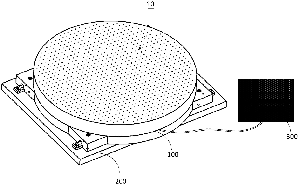
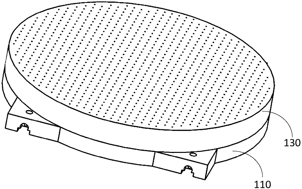
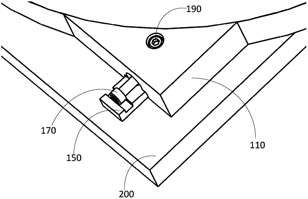
Sucking disc structure and vacuum adsorption system

A vacuum adsorption system and vacuum suction cup technology, applied in the field of precision machining, can solve the problems of low machining accuracy of parts, and achieve the effect of improving the low machining accuracy

Pending Publication Date: 2018-11-13
LASER FUSION RES CENT CHINA ACAD OF ENG PHYSICS
View PDF12 Cites 0 Cited by
  • Summary
  • Abstract
  • Description
  • Claims
  • Application Information

AI Technical Summary

Problems solved by technology

[0004] In view of this, the object of the present invention is to provide a suction cup structure and a vacuum adsorption system to improve the low processing accuracy of parts in the prior art

Method used


Image

  • Sucking disc structure and vacuum adsorption system
  • Sucking disc structure and vacuum adsorption system
  • Sucking disc structure and vacuum adsorption system

Examples


Embodiment Construction

[0038] In order to make the objectives, technical solutions, and advantages of the embodiments of the present invention clearer, the technical solutions in the embodiments of the present invention will be described clearly and completely in conjunction with the accompanying drawings in the embodiments of the present invention. Obviously, the described embodiments It is only a part of the embodiments of the present invention, not all the embodiments. The components of the embodiments of the present invention generally described and illustrated in the drawings herein may be arranged and designed in various different configurations.

[0039] Therefore, the following detailed description of the embodiments of the present invention provided in the accompanying drawings is not intended to limit the scope of the claimed invention, but merely represents selected embodiments of the present invention. Based on the embodiments of the present invention, all other embodiments obtained by thos...


PUM


Abstract

The invention provides a sucking disc structure and a vacuum adsorption system and relates to the technical field of precision machining. The sucking disc structure comprises a base disc, a vacuum sucking disc and a regulating mechanism, wherein the vacuum sucking disc is positioned at one surface of the base disc; and the regulating mechanism at least comprises a part which is positioned at one surface, far away from the vacuum sucking disc, of the base disc. When the sucking disc structure is arranged at a machine tool platform, the regulating mechanism at least comprises one part which is positioned between the base disc and the machine tool platform so that the regulating mechanism can be used for regulating the included angle between the base disc and the machine tool platform. By thearrangement, the sucking disc structure can improve the problem about relatively low machining precision of parts in the prior art.

Description

Technical field [0001] The present invention relates to the technical field of precision processing, in particular to a sucker structure and a vacuum adsorption system. Background technique [0002] With the wide application of high-quality ultra-thin parts, the development of precision machining technology has received extensive attention. Among them, in the precision machining of ultra-thin parts, the deformation of the stress will make the surface accuracy difficult to control. In order to solve the above technical problems, a vacuum chuck is generally used in the prior art to adsorb and fix the ultra-thin parts by means of vacuum adsorption, so as to ensure high processing accuracy. [0003] The inventor found that in the processing of ultra-thin parts, some parts need to be corrected for the crystal orientation angle or form a wedge surface with a slope. Therefore, a suction cup with the ability to adjust the slope is provided to ensure the processing accuracy. It is a techn...

Claims


Application Information

Patent Timeline
Patent Type & Authority Applications(China)
IPC IPC(8): B23Q3/08B23Q3/04
CPCB23Q3/04B23Q3/088B23Q2703/04
Inventor 张帅雷向阳张剑锋苏文虎张利平惠浩浩
Owner LASER FUSION RES CENT CHINA ACAD OF ENG PHYSICS
Learn More