Ultrasonic cleaning device and method for deactivated denitration catalyst
A denitration catalyst, ultrasonic cleaning technology, applied in chemical instruments and methods, cleaning methods using liquids, cleaning methods and utensils, etc., to achieve the effect of easy and flexible use, good cleaning effect, and improved cleaning effect
- Summary
- Abstract
- Description
- Claims
- Application Information
AI Technical Summary
Problems solved by technology
Method used
Image

Examples
Embodiment 1
[0042] Ultrasonic cleaning device for deactivating denitrification catalyst.
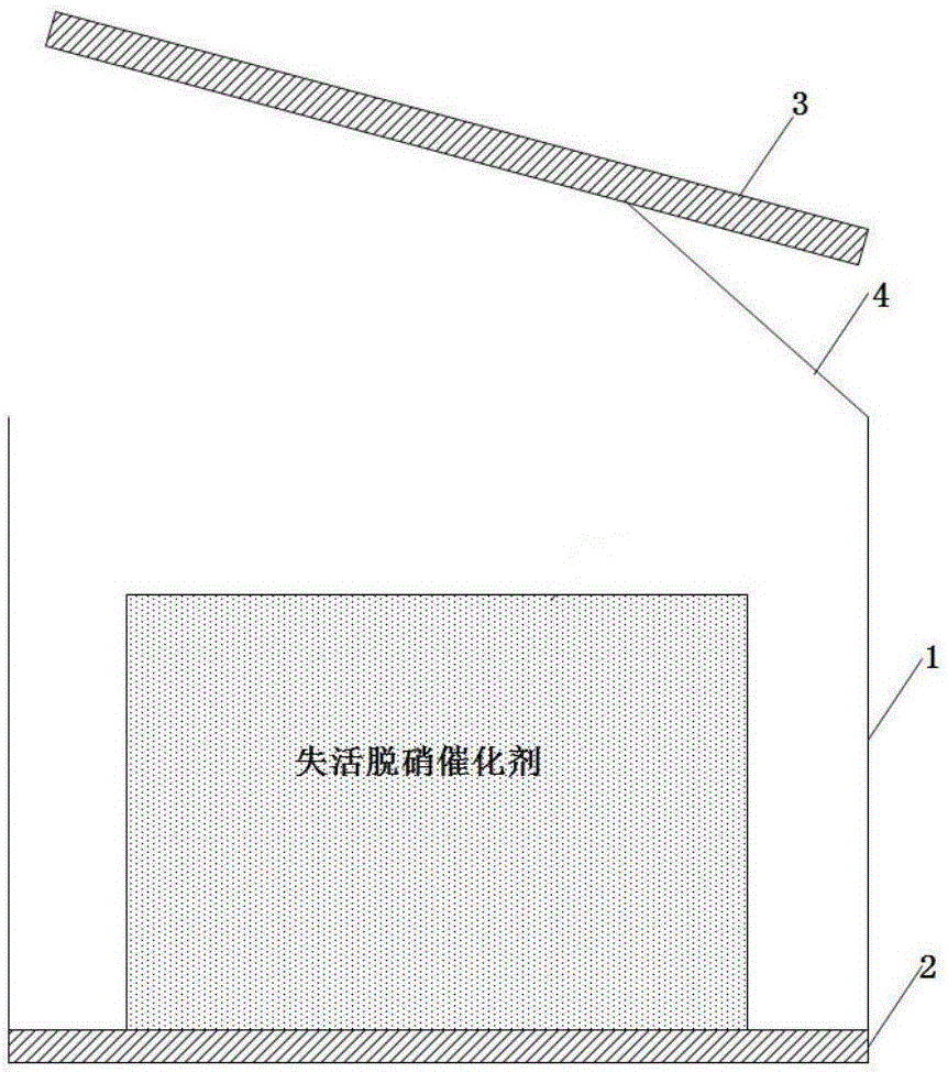
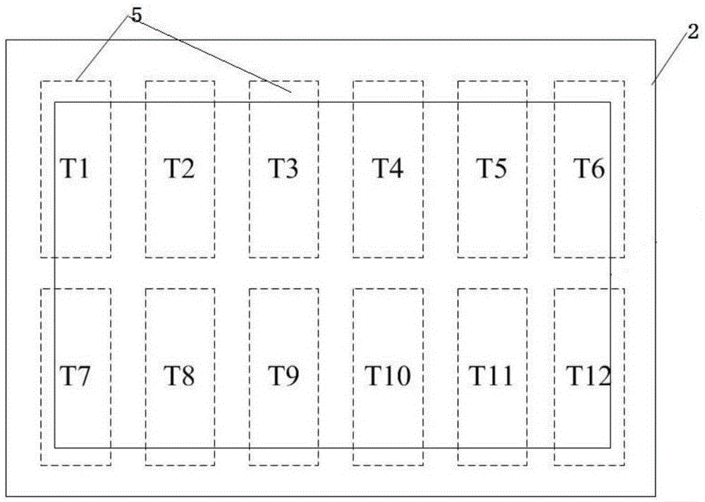
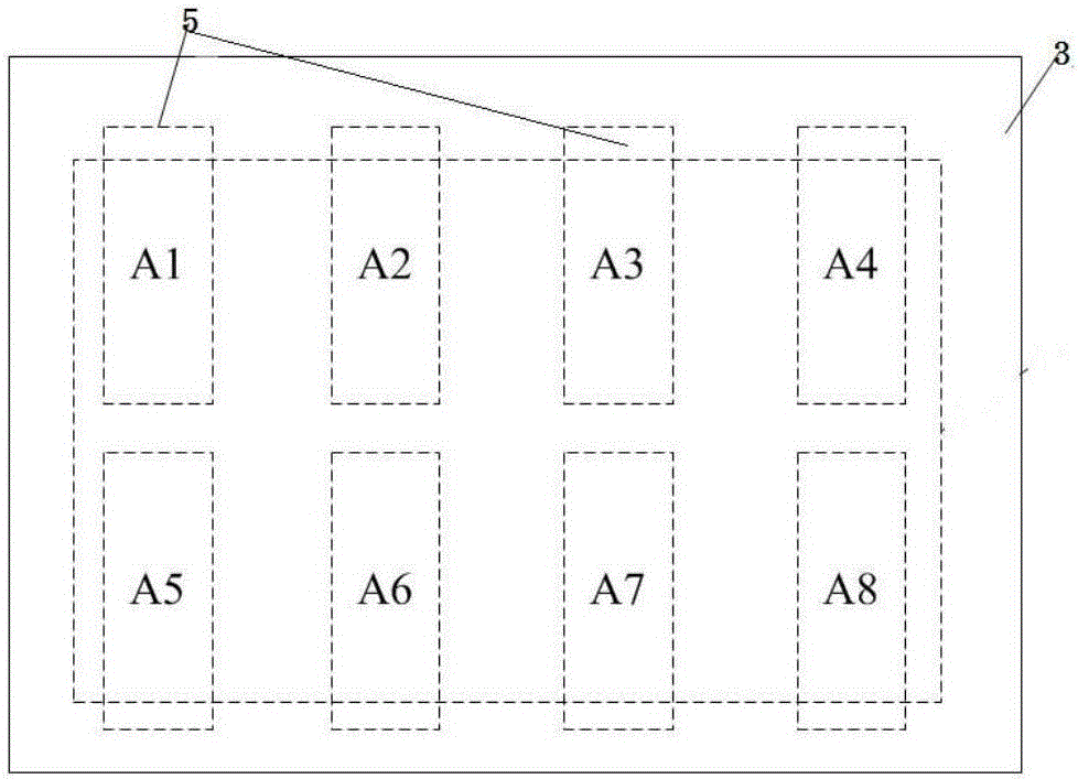
[0043] Such as figure 1 An ultrasonic cleaning device for deactivating denitration catalysts is shown, including a cleaning tank 1, a first ultrasonic system 2 and a second ultrasonic system 3, the first ultrasonic system 2 is fixed at the bottom of the cleaning tank 1, and the second ultrasonic system 3 passes through Connector 4 is movably connected to the top of cleaning tank 1, and connector 4 is specifically crawler belt; figure 2 As shown, the first ultrasonic system 2 includes 12 ultrasonic vibrating plates 5, respectively T1-T12, arranged symmetrically and orderly in two rows; as image 3 As shown, the second ultrasonic system 3 includes 8 ultrasonic vibrating plates 5, respectively A1-A8, which are arranged symmetrically and orderly in two rows; the frequencies of all ultrasonic vibrating plates 5 can be independently controlled and used separately.
Embodiment 2
[0045] The method for cleaning the deactivated denitration catalyst by using the cleaning device of Example 1.
[0046] The deactivated denitrification catalyst was selected from a coal-fired power plant in China after 24000 hours of V 2 o 5 -WO 3 / TiO 2 Honeycomb denitrification catalyst.
[0047] Include the following steps:
[0048] After removing the ash from the deactivated denitrification catalyst module, check the surface condition of the catalyst after ash removal, and determine the areas with relatively more residual ash accumulation, which are T2, T11 and A2, A8 respectively; put the catalyst in the cleaning tank, add acid cleaning Turn on the ultrasonic vibrating plates T2, T11 and A2, A8 for directional rough cleaning. The frequency of the ultrasonic vibrating plates is 40kHz, the rough washing time is 35min, and the temperature of the cleaning solution is 35°C; after the rough washing is completed, use all the ultrasonic vibrating plates. The switching freque...
Embodiment 3
[0080] The method for cleaning the deactivated denitration catalyst by using the cleaning device of Example 1.
[0081] The deactivated denitrification catalyst is selected from a coal-fired power plant in China after 23000 hours of V 2 o 5 -MoO 3 / TiO 2 Flat-plate denitration catalyst. After de-ashing the deactivated denitrification catalyst module, check the surface condition of the catalyst after de-ashing, and determine the areas with relatively more residual ash accumulation, which are T3, T9 and A2, A6 respectively. Put the catalyst in the cleaning tank, add alkaline For cleaning solution, turn on the ultrasonic vibrating plates T3, T9, A2, and A6 for directional coarse cleaning. The frequency of the ultrasonic vibrating plates is 30kHz, the rough cleaning time is 25min, and the temperature of the cleaning liquid is 50°C; after the rough cleaning is completed, put all the ultrasonic vibrating plates into use , switch the frequency of the ultrasonic vibrating plate to...
PUM
 Abstract
Description
Claims
Application Information
 - R&D Engineer
- R&D Manager
- IP Professional
- Industry Leading Data Capabilities
- Powerful AI technology
- Patent DNA Extraction
Browse by: Latest US Patents, China's latest patents, Technical Efficacy Thesaurus, Application Domain, Technology Topic.
© 2024 PatSnap. All rights reserved.Legal|Privacy policy|Modern Slavery Act Transparency Statement|Sitemap