Novel high-strength high-compactness lightweight aircraft landing gear

An aircraft landing gear, high-strength technology, applied in landing gear, aircraft parts, chassis, etc., can solve the problems of aircraft safety accidents, landing gear not working properly, etc., and achieve the effect of improving structural strength

Inactive Publication Date: 2017-03-22
TSINGHUA UNIV
View PDF5 Cites 11 Cited by
  • Summary
  • Abstract
  • Description
  • Claims
  • Application Information

AI Technical Summary

Problems solved by technology

[0003] The early aircraft landing gear generally adopts a planar four-bar linkage mechanism. When the landing gear is fully lowered, there are exactly two connecting rods in the collinear position to ensure the working attitude of the landing gear. The main bearing rod of the landing gear bears the weight of the aircraft. Most of the load, therefore, in the case of failure of the landing gear attitude maintaining structure, the landing gear will not work normally, leading to aircraft safety accidents
[0004] In order to increase the safety and reliability of the aircraft, aircraft landing gear designers at home and abroad continue to improve their schemes. However, these improvement schemes are derivatives of the traditional planar four-bar linkage and cannot completely solve the fundamental defects of the traditional landing gear.

Method used


Image

  • Novel high-strength high-compactness lightweight aircraft landing gear
  • Novel high-strength high-compactness lightweight aircraft landing gear
  • Novel high-strength high-compactness lightweight aircraft landing gear

Examples


Embodiment Construction

[0032] In order to make the object, technical solution and advantages of the present invention clearer, the implementation manner of the present invention will be further described in detail below in conjunction with the accompanying drawings.

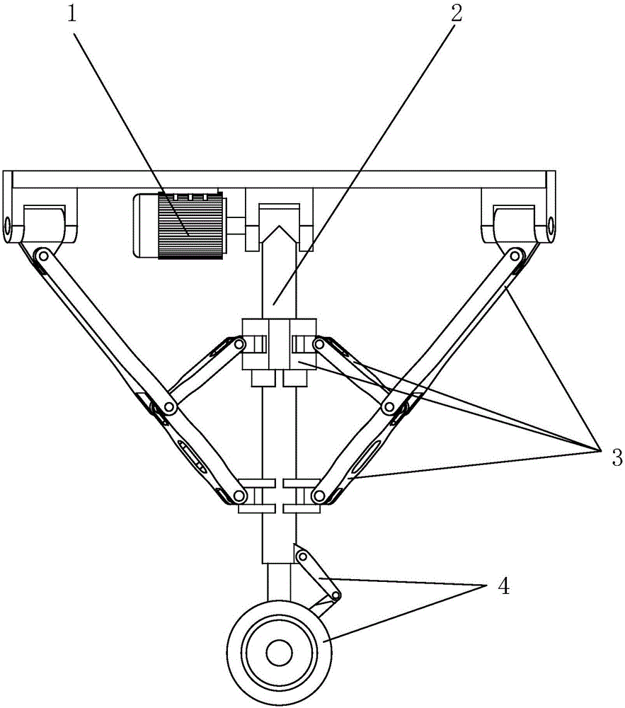
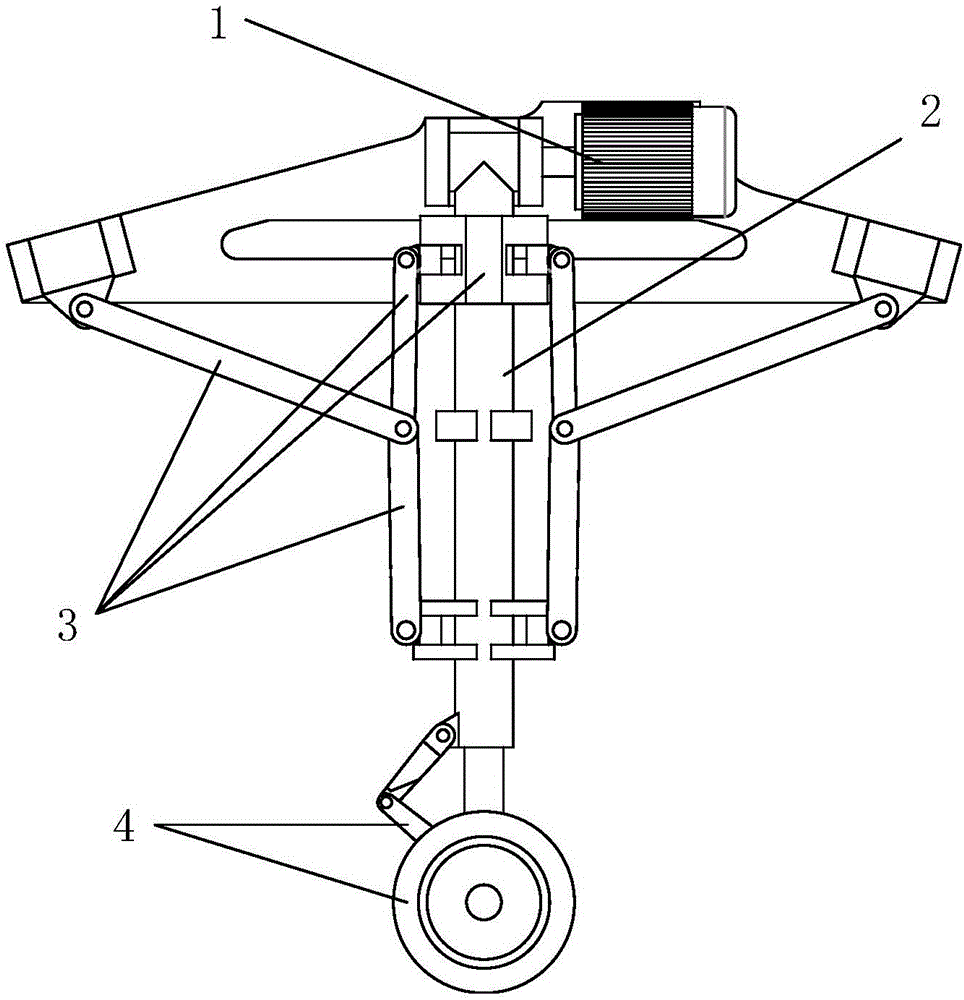
[0033] Embodiments of the present invention provide a novel high-strength, high-compact, lightweight aircraft landing gear, see Figure 1a and Figure 1b , including a drive system 1 , a main bearing rod 2 , a locking mechanism 3 and a shock absorbing system 4 .

[0034] The drive system 1 is arranged on the upper part of the main bearing rod 2 .

[0035] The main bearing bar 2 is arranged between the aircraft fuselage and the damping system 4 .

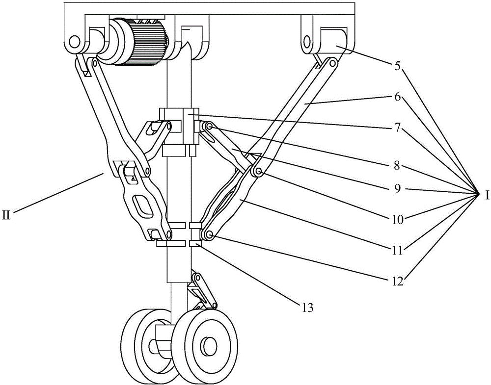
[0036] The locking mechanism 3 is arranged between the aircraft fuselage and the main bearing rod 2, and includes two identical non-coplanar kinematic chains, namely the first kinematic chain I and the second kinematic chain II.

[0037] The damping system 4 is arranged at the lower part of...


PUM


Abstract

The invention discloses a novel high-strength high-compactness lightweight aircraft landing gear. The novel high-strength high-compactness lightweight aircraft landing gear comprises a driving system, a main bearing rod, a locking mechanism and a damping system, wherein the driving system is arranged on the upper part of the main bearing rod; the main bearing rod is arranged between an aircraft fuselage and the damping system; the locking mechanism is arranged between the aircraft fuselage and the main bearing rod; the locking system comprises two identical kinematic chains which are not arranged in the same plane and respectively include a first kinematic chain and a second kinematic chain; the damping system is arranged on the lower part of the main bearing rod and comprises a damper and a pneumatic tire; and the lower end of the damper is connected with the pneumatic tire. According to the novel high-strength high-compactness lightweight aircraft landing gear disclosed by the invention, a conventional plane four-link landing gear is changed into a space four-link mechanism, and the reliable double-locking structures are a great contribution to the prior aircraft landing gear technology; and two sets of double-locking mechanisms are separated from each other and distributed symmetrically, and the safety of the aircraft landing gear is greatly improved by such a redundant design.

Description

technical field [0001] The invention relates to the field of aircraft design, in particular to a novel high-strength, high-compact, lightweight aircraft landing gear. Background technique [0002] Aircraft landing gear is an important safety functional part of the aircraft. It is the main load-bearing component when the aircraft takes off, lands, taxis on the ground and parks. The landing gear must absorb and dissipate the energy from the impact with the ground during the landing and taxiing process of the aircraft. To ensure the safety of the aircraft when landing and taxiing, the performance level of the landing gear is directly related to the overall performance and flight safety of the aircraft, and has always been one of the key components that large aircraft manufacturing companies at home and abroad are committed to improving. [0003] The early aircraft landing gear generally adopts a planar four-bar linkage mechanism. When the landing gear is fully lowered, there ar...

Claims


Application Information

Patent Timeline
Patent Type & Authority Applications(China)
IPC IPC(8): B64C25/04B64C25/34B64C25/58
CPCB64C25/04B64C25/34B64C25/58B64C2025/345
Inventor 赵景山罗宏图郭凯文黄京汲星辰
Owner TSINGHUA UNIV
Why Eureka
Try Eureka