
Fully automatic invisible zipper upper movable code equipment

A technology of invisible zipper and movable code, which is applied in the direction of transportation, packaging, conveyors, etc., and can solve problems such as broken limit codes and molds that cannot complete processing.

Active Publication Date: 2019-02-12
WENZHOU HONGYE PRECISE MACHINERY
View PDF5 Cites 0 Cited by
  • Summary
  • Abstract
  • Description
  • Claims
  • Application Information

AI Technical Summary

Problems solved by technology

Since the limit codes on the limit code conveying track are arranged side by side, one is closely adjacent to the other, when one limit code enters the mold, the other limit code that follows it may also be squeezed into the mold. In the mold, the mold cannot complete the processing and the limit code will be damaged

Method used


Image

  • Fully automatic invisible zipper upper movable code equipment
  • Fully automatic invisible zipper upper movable code equipment
  • Fully automatic invisible zipper upper movable code equipment

Examples


Embodiment Construction

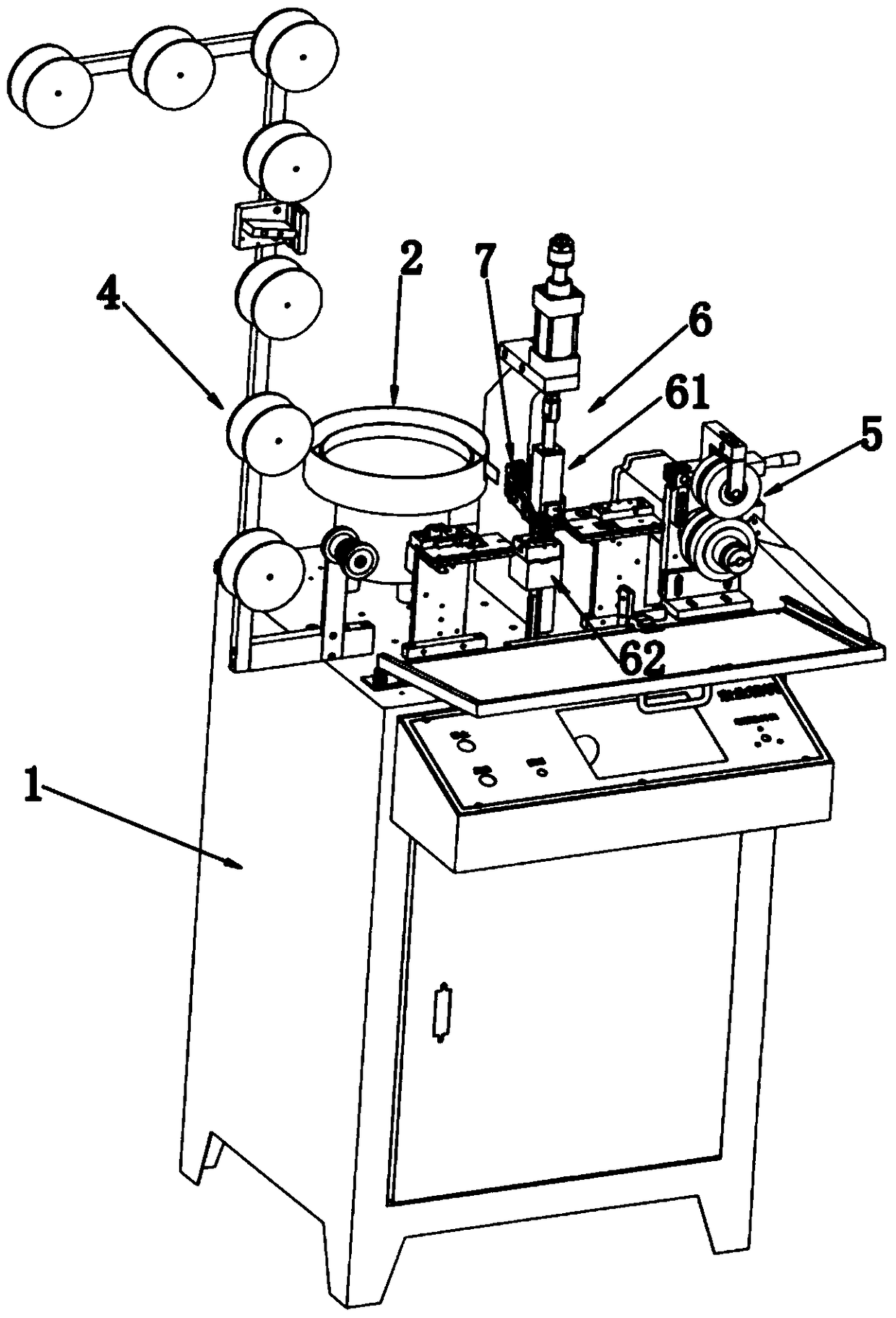
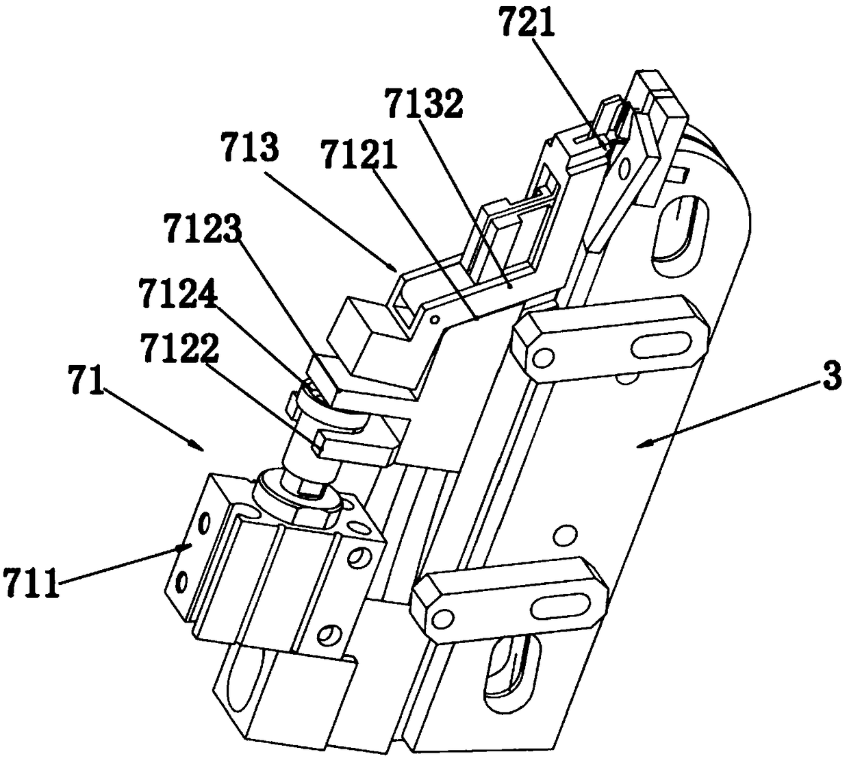
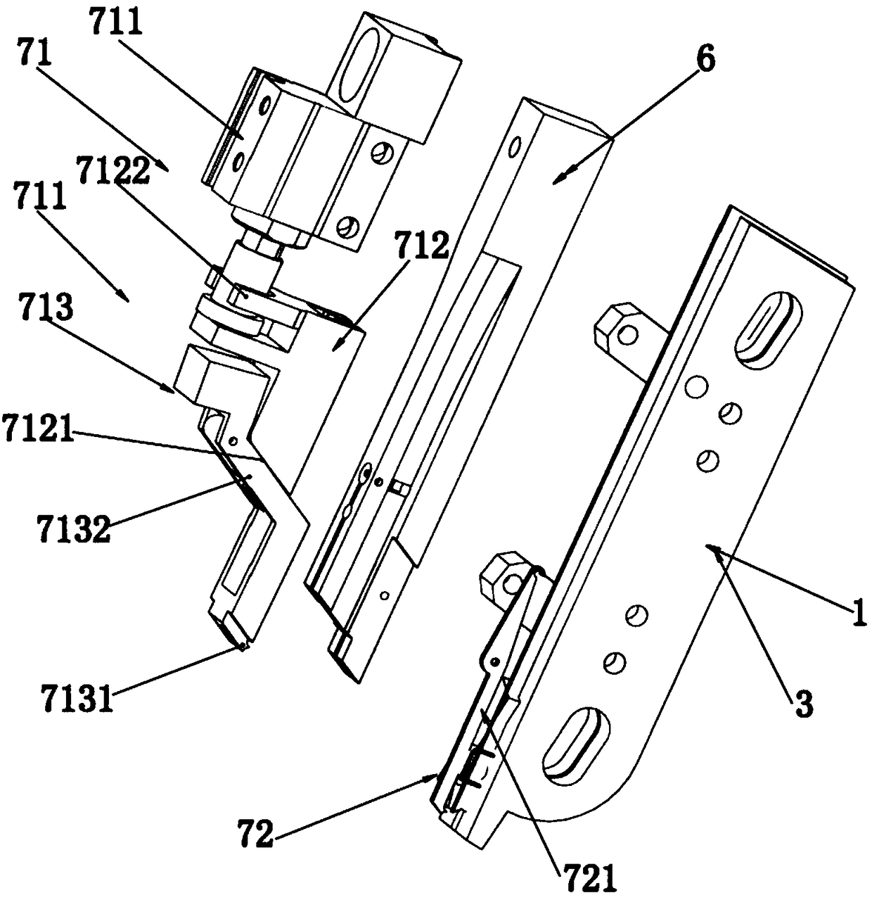
[0028] Such as figure 1 — Figure 7A fully automatic movable code device on invisible zippers shown includes a body 1, a vibrating tray 2 arranged on the body 1, a limit code conveying track 3 connected with the vibrating tray 2, a zipper belt conveying mechanism 4, a zipper The belt traction mechanism 5 and the stamping upper code mold 6 located between the zipper belt conveying mechanism 4 and the zipper belt traction mechanism 5, the limit code conveying assembly 7 is arranged between the limit code conveying track 3 and the stamping upper code mold 6, The limit code conveying assembly 7 includes a limit code one by one feed positioning device 71 and a limit code limit device 72. The clamping bar 721 that swings on the bit code conveying track 3, one axial end of the clamping bar 721 is a clamping limit end 7211, and the other end is an elastic tension end 7212, between the clamping limit end 7211 and the elastic tension end 7212 Between is the hinged end 7213 that is hin...


PUM


Abstract

The invention relates to zipper code loading equipment, in particular to full-automatic conceal zipper movable code loading equipment. According to the technical scheme, the full-automatic conceal zipper movable code loading equipment comprises a machine body, a vibration tray, a limiting code conveying rail, a zipper belt conveying mechanism, a zipper belt traction mechanism and a punching code loading mold; a limiting code conveying assembly is arranged between the limiting code conveying rail and the punching code loading mold, and includes a limiting code one-by-one feeding and positioning device and a limiting code limiting device; the limiting code limiting device includes a clamping bar erected on the limiting code conveying rail and suffered from external force to swing on the limiting code conveying rail; and the limiting code one-by-one feeding and positioning device includes a driving source erected above the limiting code conveying rail, a slide base and a clamping arm hinged with the slide base. By means of the technical scheme, the full-automatic conceal zipper movable code loading equipment urges limiting codes to enter the mold one by one in sequence, and is simple in structure and high in sensitivity.

Description

technical field [0001] The invention relates to a zipper coding device, in particular to a fully automatic invisible zipper coding device. Background technique [0002] The invisible zipper is mainly used in down jackets, jeans and high-end jackets. It has two chain belts, and the chain teeth of the two chain belts are arranged alternately. The invisible zipper has an activity limit code that is sleeved on the chain belt and can slide on the chain belt. The chain belt of the traditional invisible zipper and the limit code (bottom stop) on it are assembled manually, which not only has low assembly efficiency, but also has high labor costs. With the continuous research and development of technicians in this field, some automatic assembly equipment has appeared on the market. [0003] This type of equipment has a vibrating feeding tray, a stamping upper die connected to the vibrating feeding tray through the limit code conveying track. During the assembly process, the limit ...

Claims


Application Information

Patent Timeline
Patent Type & Authority Patents(China)
IPC IPC(8): B65G25/08
CPCB65G25/08
Inventor 张岳恩郑祥鹏
Owner WENZHOU HONGYE PRECISE MACHINERY
Learn More