
Sliding table mechanism

A sliding and sliding table technology, applied in conveyors, mechanical conveyors, transportation and packaging, etc., can solve the problems of large volume, long travel of conveying mechanism, large space occupation, etc., and achieve good application prospects, low cost and saving. The effect of space occupation

Inactive Publication Date: 2017-03-22
ANHUI RUIXIANG IND
View PDF7 Cites 5 Cited by
  • Summary
  • Abstract
  • Description
  • Claims
  • Application Information

AI Technical Summary

Problems solved by technology

[0002] For the transportation of some larger auto parts, it is often conveyed by a conveying mechanism. In the prior art, the conveying mechanism has a long stroke, a large volume, and a large space occupation, which is not convenient for arrangement in the workshop.

Method used


Image

  • Sliding table mechanism
  • Sliding table mechanism
  • Sliding table mechanism

Examples


Embodiment Construction

[0020] The specific implementation manner of the present invention will be described in further detail below by describing the embodiments with reference to the accompanying drawings.

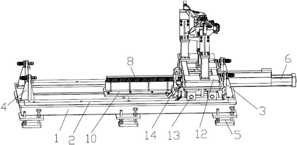
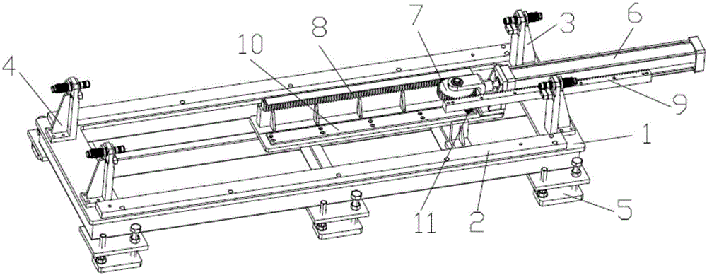
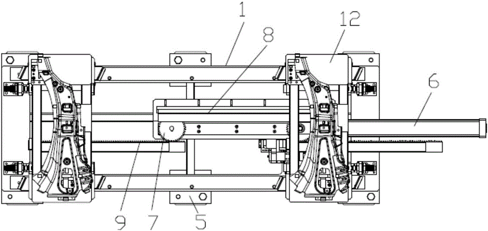
[0021] The sliding table mechanism of the present invention, such as figure 1 , 2 As shown, a base 1 is included, and a slide table 12 supporting the material is provided on the base 1. When in use, the material is fixedly clamped on the slide 12, and is transported forward with the slide 12. The base 1 is provided with a sliding guide rail 2 for the slide table 12 to slide. In the present invention, two sliding guide rails 2 are arranged in parallel, and a sliding wheel 13 that can slide along the sliding guide rails 2 is provided under the sliding platform 12 . The slide table 12 realizes horizontal sliding by rolling the sliding wheels 13 on the slide guide rail 2, and a small driving force can ensure the stable conveyance of the slide table 12.

[0022] In the present invention, the slid...


PUM


Abstract

The invention discloses a sliding table mechanism. The sliding table mechanism comprises a base. The base is provided with a sliding table used for supporting materials and parts. The sliding table can move along sliding guide rails arranged on the base. The base is further provided with a conveying cylinder used for pushing the sliding table to move. The extension bar end of the conveying cylinder is connected with a gear. The base is provided with a fixed rack which is arranged in the conveying direction of the sliding table and engaged with the gear. A sliding rack arranged in the conveying direction of the sliding table is connected below the sliding table. The sliding rack and the gear are in gear engagement. By the adoption of the sliding table mechanism, large-stroke sliding push can be realized through the short conveying cylinder, the cost is low, occupied space is saved, and the application prospects are good.

Description

technical field [0001] The invention belongs to the technical field of conveying devices, and more specifically relates to a double-rack sliding table mechanism. Background technique [0002] The transportation of some larger auto parts is often carried by a conveying mechanism. In the prior art, the conveying mechanism has a long stroke, a large volume, and a large space occupation, which is not convenient for arrangement in the workshop. Contents of the invention [0003] The purpose of the present invention is to solve the problems existing in the prior art, and provide a sliding table mechanism with a clever structure, a small space occupation, and a large sliding distance. [0004] In order to achieve the above object, the technical solution adopted by the present invention is: the provided sliding platform mechanism is characterized in that it includes a base, and a sliding platform for supporting materials is arranged on the base, and the sliding platform can be arr...

Claims


Application Information

Patent Timeline
Patent Type & Authority Applications(China)
IPC IPC(8): B65G35/00
CPCB65G35/00
Inventor 吴守军程春霞
Owner ANHUI RUIXIANG IND
Learn More