
Panel for sliding lock

A sliding lock and panel technology, which is applied in building locks, buildings, building structures, etc., can solve the problems of increased rack and pinion wear, affecting the service life of locks, and shaking of sliding covers, so as to reduce lateral force and slide Smooth, stable and reliable results

Active Publication Date: 2017-03-22
广东海尔智能科技有限公司
View PDF9 Cites 2 Cited by
  • Summary
  • Abstract
  • Description
  • Claims
  • Application Information

AI Technical Summary

Problems solved by technology

However, the way of elastic conflict obviously still cannot solve or improve the gap between the slide cover and the panel, and still causes the slide cover to shake, which in turn leads to assembly accuracy of the rack and pinion, increased wear of the rack and pinion, and transmission problems. Affect the service life of the lock

Method used


Image

  • Panel for sliding lock
  • Panel for sliding lock
  • Panel for sliding lock

Examples


Embodiment Construction

[0023] The following will clearly and completely describe the technical solutions in the embodiments of the present invention with reference to the accompanying drawings in the embodiments of the present invention. Obviously, the described embodiments are some of the embodiments of the present invention, but not all of them. Based on the embodiments of the present invention, all other embodiments obtained by persons of ordinary skill in the art without creative efforts fall within the protection scope of the present invention.

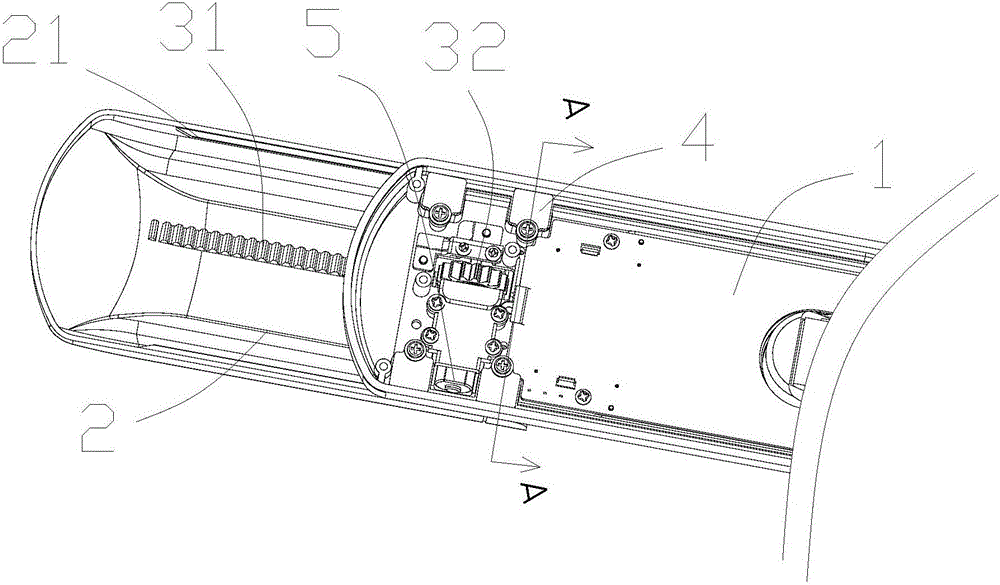
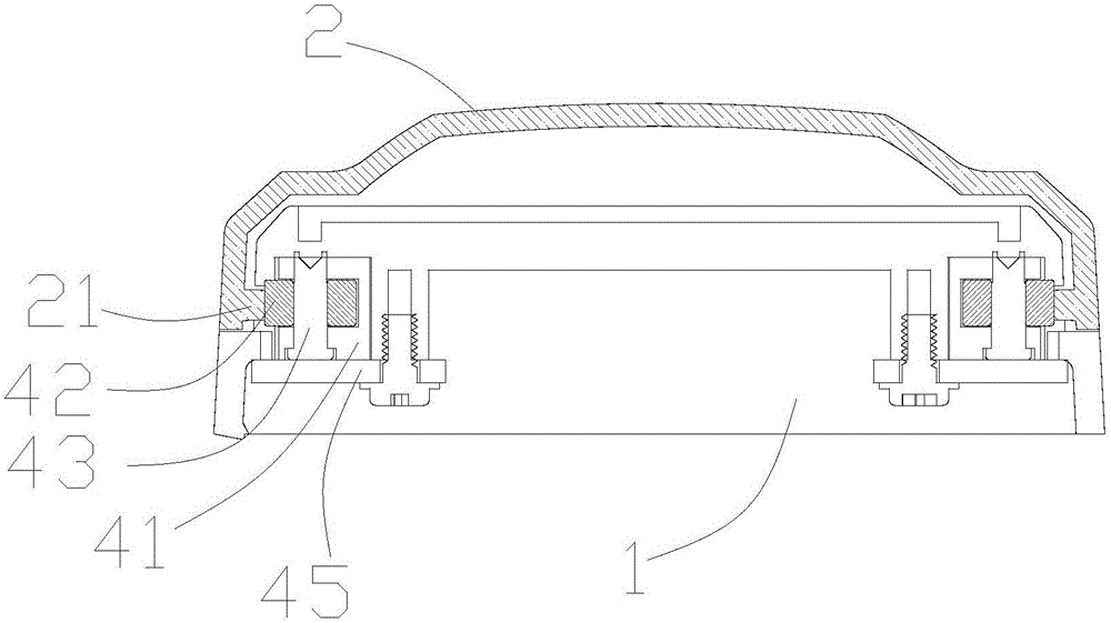
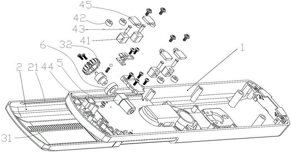
[0024] refer to figure 1 , a sliding lock panel, comprising a panel main body 1 and a sliding cover 2 slidably arranged on the panel main body 1, a sliding mechanism is arranged between the sliding cover 2 and the panel main body 1, and the sliding mechanism includes a rack 31 and The gear 32 and the panel body 1 are also provided with an adjustment mechanism 4 capable of adjusting the assembly gap between the slide cover 2 and the panel body 1 . As a...


PUM


Abstract

The invention discloses a panel for a sliding lock. The panel comprises a main panel body and a sliding cover glidingly arranged on the main panel body; a sliding mechanism is arranged between the sliding cover and the main panel body and comprises a rack and a gear which mesh with each other; an adjusting mechanism capable of adjusting the assembly gap between the sliding cover and the main panel body is further arranged on the main panel body; and the adjusting mechanism is adjusted, so that the sliding cover makes close contact with the main panel body. The assembly gap between the sliding cover and the main panel body can be adjusted, so that sliding of the sliding cover relative to the main panel body is very accurate and stable, the gear and the rack are protected, the service life of the lock is prolonged, the production cost is reduced, and the assembly universality and applicability of the sliding cover and the main panel body are improved.

Description

technical field [0001] The present invention relates to a sliding lock panel. Background technique [0002] As smart locks are more and more widely used, especially the precision of the components on the panel body of the smart lock continues to increase, the maintenance costs of these components continue to increase, so a movable sliding cover is needed to hide and protect these components. [0003] In the prior art, most sliding covers need to be opened and closed manually. When users use it, they push open the cover before operation, but they often forget to close the cover after the operation is completed, which is inconvenient to use and cannot protect the precision parts well. In order to make the user have a better experience, the opening and closing function of the sliding cover can usually be realized by an electric device, and at the same time, the opening and closing of the sliding cover can be realized manually when the power is cut off. [0004] The transmissi...

Claims


Application Information

Patent Timeline
Patent Type & Authority Applications(China)
IPC IPC(8): E05B17/18
CPCE05B17/186
Inventor 宋庆华杜可伟卢长志
Owner 广东海尔智能科技有限公司
Learn More