Waste Gasification Melting Combustion System

A gasification melting and combustion system technology, applied in the direction of combustion type, combustion method, incinerator, etc., can solve the problems of lower heat conversion efficiency, small amount of garbage disposal, and difficulty in matching the rhythm of the separation stage, etc., to improve heat exchange efficiency, A large amount of garbage can be processed to ensure the effect of heat reduction rate

Active Publication Date: 2018-11-27
CHONGQING SANFENG ENVIRONMENTAL IND GRP +1
View PDF12 Cites 0 Cited by
  • Summary
  • Abstract
  • Description
  • Claims
  • Application Information

AI Technical Summary

Problems solved by technology

[0007] 2. With the increasing amount of waste generated and piled up like mountains, the processing capacity must be effectively increased in order to meet market demand
[0010] Existing incinerators such as the following two invention patents: multi-column segmented drive compound domestic waste incinerator (ZL200710092508.9) and two-stage waste incinerator (ZL201010268376.2) Unsolved problems: waste heat treatment mode Relatively backward, it is only the process of drying-combustion-burning, solid combustion to release heat; the thermochemical reaction in the furnace is dominated by oxidation reaction, supplemented by reduction reaction, which is easy to produce secondary pollutants; when waste is burned in the furnace, the peroxygen coefficient Large, large amount of primary air and secondary air supply, high dust content in flue gas, great impact on heat energy recovery system and flue gas treatment system, easy to accumulate dust, large amount of flue gas, reducing heat conversion efficiency; There is no separate gasification furnace and ember furnace, so garbage can only be treated in batches, and large-scale continuous gasification and incineration of waste cannot be realized, and the amount of garbage treated is small
Such as a plasma-assisted heating melting gasification reactor (CN201410744643.7), waste gasification melting furnace (CN201280068994.X), municipal solid waste oxygen top blowing direct melting gasification combustion and its power generation technology (CN01107088.9) and others The tank-type gasification-melting centralized treatment technology has unresolved problems: the heat treatment mode of waste is relatively advanced, but it mainly continues the idea of ​​fixed bed or fluidized bed to carry out drying-pyrolysis-gasification-combustion (also without combustion) )-melting, the continuity of the heat treatment process is not good, it is difficult to match the treatment rhythm of each stage, and the heat recovery and utilization link is not considered enough, the economy is poor, and it is impossible to realize large-scale continuous gasification and melting treatment of waste, and the treatment capacity is small. And the processing of molten slag is not perfect
Such as a rotary kiln gasification, plasma melting domestic waste graded gasification system (CN201520578876.4), a method for producing combustible gas by melting and gasifying domestic waste in a rotary kiln (CN200910218227.2), waste gasification and fly ash high temperature Melting treatment device and method (CN200710144924.9) and other tank-type separation treatment technologies, the unresolved problem: the waste heat treatment mode is relatively advanced, but it mainly continues the idea of ​​fixed bed or fluidized bed to carry out drying-pyrolysis- Gasification-combustion (also without combustion)-melting, the main gasification and melting stages are separated into different equipment, the heat treatment process is more continuous, but the rhythm between the separation stages is still difficult to match, and the recovery of heat Insufficient consideration of the utilization link, poor economic efficiency, large-scale continuous gasification and melting of waste cannot be realized, the processing volume is small, and the treatment of molten slag is not perfect

Method used


Image

  • Waste Gasification Melting Combustion System
  • Waste Gasification Melting Combustion System
  • Waste Gasification Melting Combustion System

Examples


Embodiment Construction

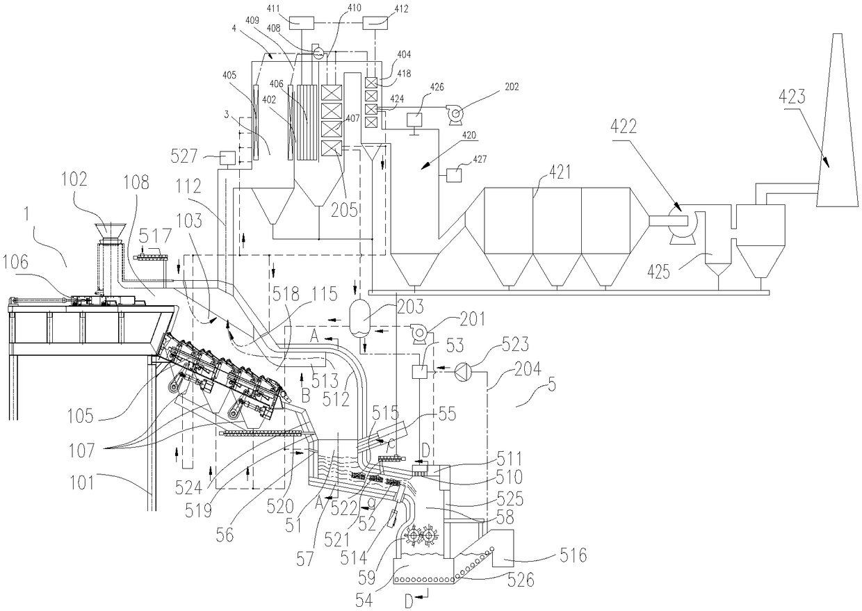
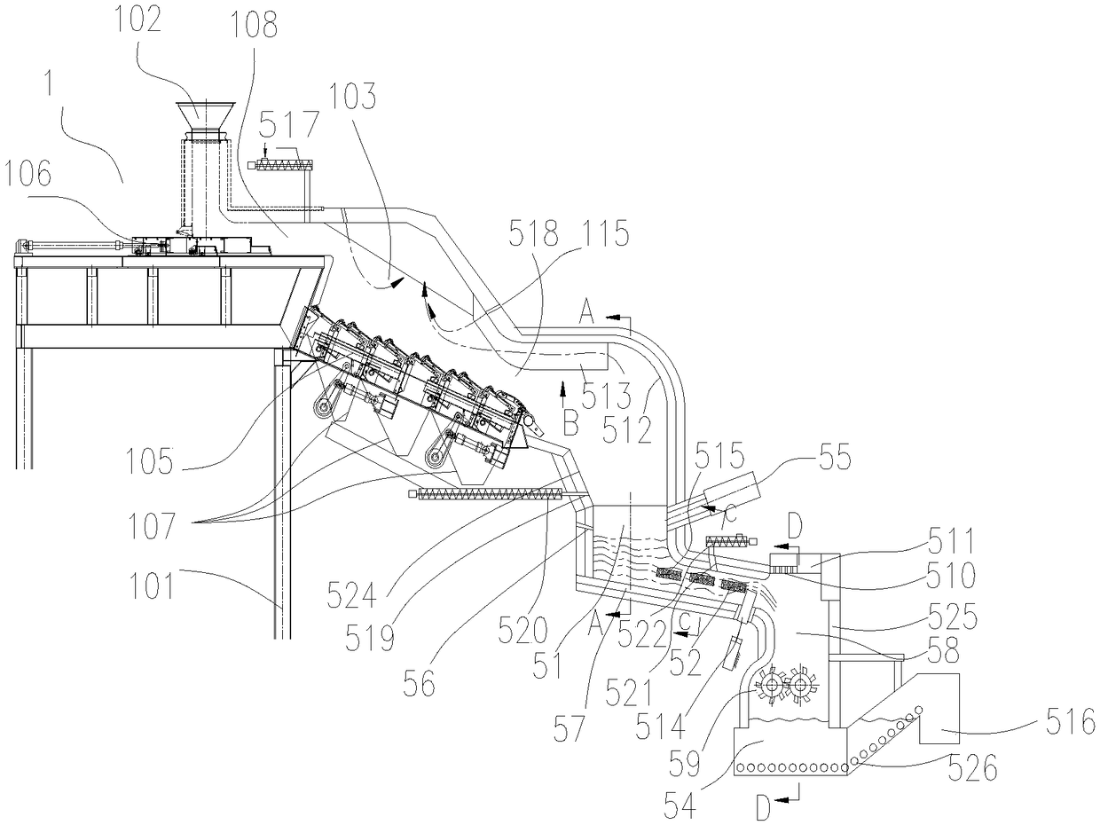
[0050] see Figure 1 to Figure 9 , which is a preferred embodiment of the waste gasification melting combustion system. This embodiment includes a waste gasification and melting furnace and a boiler system. The waste gasification and melting furnace includes a furnace frame, and a feed bin, a gasification furnace, and a melting and solidification treatment system are sequentially arranged on the furnace frame along the feeding direction , the discharge end of the melting and solidification treatment system is the glass body slag discharge port.

[0051] The grate is provided with a waste main pusher, and the waste main pusher is located below the feed bin, and is used to push the waste in the feed bin into the gasifier. The feed bin, A stockpile sealing section is provided between the gasifiers, and a base material feeding port is provided on the top wall of the stockpile sealing section, and the base material feeding port is connected to a base material feeding device, and t...


PUM


Abstract

The invention discloses a waste gasification melting combustion system. The system is used for treating garbage, is higher in garbage conveying capacity, is higher in garbage treatment quantity, can reduce the heat loss and improve the heat exchange efficiency, is higher in heat recovery efficiency, and can effectively reduce the pollutant discharge. The waste gasification melting combustion system comprises a waste gasification melting furnace and a boiler system; the waste gasification melting furnace includes a furnace frame, and a feeding bin, a gasification furnace and a melting curing system arranged on the furnace frame in the feeding direction in sequence; the melting curing system includes a melting hearth, a laminar channel, a water cooling crushing system and a water seal deslagging system arranged in sequence in the feeding direction; a high-temperature combustor and a gasifying agent inlet are arranged on the side wall of the melting hearth; the water cooling crushing system includes a water cooling system, a water cooling cavity and a glass body crusher; and a discharge end of the water seal deslagging system is connected with a glass body slag discharge port.

Description

technical field [0001] The invention belongs to the technical field of waste treatment, in particular to a waste gasification melting combustion system. Background technique [0002] Existing waste treatment technologies mainly include incineration, sanitary landfill, composting, and waste recycling. Among the conventional waste treatment technologies, incineration treatment has the advantages of obvious reduction effect, complete harmlessness, small land occupation, utilization of waste heat energy, and less secondary pollution, which meets the strategic requirements of my country's sustainable development. However, with the continuous improvement of environmental protection requirements at home and abroad, how to strengthen the control of secondary pollution is particularly important. Therefore, waste pyrolysis gasification incineration technology is gradually pushed to the road of industrial application, especially for various domestic wastes, various incineration techno...

Claims


Application Information

Patent Timeline
Patent Type & Authority Patents(China)
IPC IPC(8): F23G5/027F23G5/04F23G5/20F23G5/38F23G5/44F23G5/46F23J1/08F23J7/00
CPCF23G5/027F23G5/04F23G5/20F23G5/38F23G5/44F23G5/46F23G2201/302F23G2201/304F23G2206/10F23G2206/20F23G2209/30F23J1/08F23J7/00
Inventor 徐明肖大志刘德绍林顺洪李长江杨鲁柏继松田野阳小燕吕全伟
Owner CHONGQING SANFENG ENVIRONMENTAL IND GRP
Why Eureka
Try Eureka