Single-frame particle imaging tachymeter suitable for high-speed flow filed and speed measurement method

A high-speed flow field, high-speed technology, applied in the direction of fluid velocity measurement, velocity/acceleration/impact measurement, instruments, etc., can solve the problems of application limitation, complicated velocity calculation, shortening the time for taking two images, etc.

Inactive Publication Date: 2017-03-22
HARBIN ENG UNIV
View PDF6 Cites 14 Cited by
  • Summary
  • Abstract
  • Description
  • Claims
  • Application Information

AI Technical Summary

Problems solved by technology

However, when this method measures the high-speed flow field, it is necessary to shorten the time for taking pictures of the two images, which increases the requirements for the controller under certain circumstance

Method used


Image

  • Single-frame particle imaging tachymeter suitable for high-speed flow filed and speed measurement method

Examples


Embodiment Construction

[0012] The present invention is described in more detail below in conjunction with accompanying drawing example:

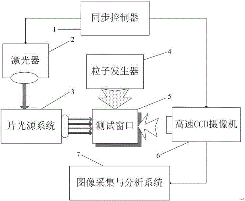
[0013] combine figure 1 , including a synchronous controller 1, a laser 2, a sheet light source system 3, a particle generator 4, a test window 5, a high-speed CCD camera 6, and an image acquisition and analysis system 7; the synchronous controller 1 controls the laser 2 so that the laser 2 emits high-intensity pulsed laser, the laser passes through the sheet light source system 3 to form a sheet light source to irradiate the test window 5, at the same time, the particle generator 4 continuously fills the test flow field with tracer particles through the test window 5, and the high-speed CCD camera 6 is also synchronously controlled Under the control of the device 1, a single-frame image of the high-speed flow field is captured through the test window 5, and the captured image information is transmitted to the image acquisition and analysis system 7.

[0014] The...


PUM


Abstract

The invention aims to provide a single-frame particle imaging tachymeter suitable for a high-speed flow field and a speed measurement method. The single-frame particle imaging tachymeter includes a laser, a high-speed CCD camera, a synchronous controller, a particle generator, a sheet light source system, a test window and an image acquisition and analysis system, the synchronous controller is connected with the laser and the high-speed CCD camera, a test flow field is inside the test window, pulse laser generated by the laser is irradiated on the test window through the sheet light source system, the particle generator is connected with the test window, the high-speed CCD camera faces the test window, and the image acquisition and analysis system is connected with the high-speed CCD camera. The single-frame particle imaging tachymeter suitable for the high-speed flow field can well solve the problem of influence on measurement brought by the fact that a synchronizer is difficult to accurately control a pulse interval of a laser and a photographing interval of a high-speed CCD camera when a traditional PIV speed measurement system is applied to a high-speed flow field, and avoids the problem that related particles are searched from two images to perform speed calculation.

Description

Technical field [0001] The invention relates to a particle image velocity measuring device and method. Background technique [0002] Flow field is the space occupied by fluid movement. Flow fields are widely used. With the advancement of science and technology, high-speed flow fields are gradually involved in many technical fields. For example, jet aircraft tail nozzles are high-speed flow fields. A clear and accurate understanding of the velocity distribution in each interval in the high-speed flow field is of great significance to research and solve problems. Therefore, there is an urgent need for a global velocity measurement instrument for high-speed flow fields. [0003] The initial flow field velocity test was mainly based on single-point testing, including hot-wire wind speed measurement method and laser Doppler speed measurement method. The hot-wire wind speed measurement method uses a thin metal wire that is heated by electricity as the probe and places it at the de...

Claims


Application Information

Patent Timeline
IPC IPC(8): G01P5/22
CPCG01P5/22
Inventor 杨晓涛谢文强王金鑫张子鉴李瑶瑶夏文
Owner HARBIN ENG UNIV
Why Eureka
Try Eureka