
Appointed object tracking method

An object, tracking target technology, applied in image data processing, instruments, computing and other directions, can solve problems affecting tracking accuracy and stability, limited target expression ability, inability to detect changes in target size, etc., to improve the accuracy rate , Improve the tracking effect

Active Publication Date: 2017-03-22
SHENZHEN SENSETIME TECH CO LTD
View PDF3 Cites 16 Cited by
  • Summary
  • Abstract
  • Description
  • Claims
  • Application Information

AI Technical Summary

Problems solved by technology

However, due to the use of traditional features, its target expression ability is still limited
At the same time, if the target size changes during the tracking process, the method cannot detect the change of the target size, which will affect the tracking accuracy and stability.

Method used


Image

  • Appointed object tracking method
  • Appointed object tracking method
  • Appointed object tracking method

Examples


Embodiment 1

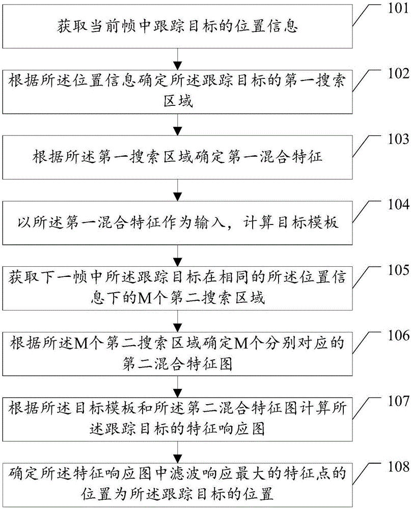
[0035] An example of the invention provides a method for tracking a designated object. like figure 1 As shown, the designated object tracking method in the embodiment of the present invention includes:

[0036] Step 101, obtaining the position information of the tracking target in the current frame;

[0037]In step 101, the designated object tracking device acquires position information of a tracking target in a current frame. In practical applications, when the tracking video is played in real time, the user marks the current frame in the tracking video in real time, marks the rectangular frame of the tracking target, and specifies the object tracking device to obtain the corresponding position information of the tracking target in the rectangular frame.

[0038] Specifically, the location information includes: the center point coordinates (x, y) of the tracking target, width information w, and height information h.

[0039] Step 102. Determine a first search area for the ...

Embodiment 2

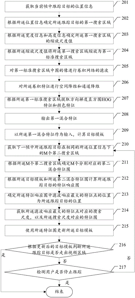
[0068] see figure 2 , in practical applications, since the hardware resources of the specified target tracking system are generally very limited, other tasks must be processed while completing the target tracking task, so this type of algorithm should not occupy too much computing and storage resources. The embodiment of the invention has been optimized accordingly, specifically including:

[0069] Step 201, obtaining the position information of the tracking target in the current frame;

[0070] In step 201, a designated object tracking device acquires position information of a tracking target in a current frame. In practical applications, when the tracking video is played in real time, the user marks the current frame in the tracking video in real time, marks the rectangular frame of the tracking target, and specifies the object tracking device to obtain the corresponding position information of the tracking target in the rectangular frame.

[0071] Specifically, the locat...


PUM


Abstract

An appointed object tracking method disclosed by the present invention comprises the steps of obtaining the position information of a tracking target in a current frame, determining a first search area of the tracking target according to the position information, determining a first mixed characteristic according to the first search area, calculating a target template by taking the first mixed characteristic as the input, obtaining M second search areas of the tracking target in the next frame under the same position information, determining M respectively corresponding second mixed characteristic graphs according to the M second search areas, and calculating a characteristic response graph of the tracking target according to the target template and the second mixed characteristic graphs; determining the position of a characteristic point having the maximum filtering response in the characteristic response graph as the position of the tracking target.

Description

technical field [0001] The invention relates to the technical field of intelligent monitoring, in particular to a method for tracking a designated object. Background technique [0002] Specified object tracking is a hotspot and basic problem in the field of computer vision and pattern recognition. The so-called specified object tracking means that the user can specify a target in the input video, mark the position of the target in the video, the size of the target rectangle and the size of the target in the video. In the initial frame, the tracking system can start tracking the target specified by the user at the second frame of video after the initial frame of the input video, and output the position coordinates and the size of the rectangular frame of the target in the video after each frame of tracking is completed. Designated object tracking and designated object tracking systems can be widely used in many fields of industrial production and life, including intelligent r...

Claims


Application Information

Patent Timeline
IPC IPC(8): G06T7/33
CPCG06T2207/20024
Inventor 马政刘俊卢宇张伟
Owner SHENZHEN SENSETIME TECH CO LTD
Learn More