Adaptive array

a radar array and adaptive technology, applied in the field of radar arrays, can solve the problems of degrading the detection and tracking performance of radar systems, and expensive radar arrays, and achieves the effects of good detection and tracking performance, easy manufacturing, and low cos

Active Publication Date: 2006-07-27
RAYTHEON CO
View PDF9 Cites 42 Cited by
  • Summary
  • Abstract
  • Description
  • Claims
  • Application Information

AI Technical Summary

Benefits of technology

[0015] In accordance with the present invention, an adaptive antenna array includes a plurality of subarrays, each one of the plurality of subarrays comprised of elements. The elements of the plurality of subarrays are arranged in element rows and element columns, and the plurality of subarrays are arranged in subarray rows and subarray columns. Some of the subarray rows have a different number of element rows than others of the subarray rows. Alternatively or in addition, some of the subarray columns have a different number of element columns than others of the subarray columns. Each of the plurality of subarrays has a respective phase center forming a plurality of phase centers at different phase center positions substantially on a plane. The different phase center positions are non-uniformly spaced from each other along at least one principal dimension in the plane. With this particular arrangement, the adaptive antenna array can be used to provide good detection and tracking performance while being inexpensive and easy to manufacture.
[0016] In accordance with another aspect the present invention, a radar system includes an adaptive array as described above. With this particular arrangement, the radar system has an adaptive antenna array that can be used to provide good detection and tracking performance, and provides an antenna array that is inexpensive an easy to manufacture.
[0017] In accordance with yet another aspect of the present invention, a method of adapting a radar array includes generating complex adaptive weights associated with the radar array, and applying the complex adaptive weights to the radar array. With this particular arrangement, the method makes use of an adaptive antenna array that can be used to provide good detection and tracking performance, the antenna array being inexpensive an easy to manufacture.

Problems solved by technology

As is known, jammers emitting radar energy can degrade target detection and tracking performance of radar systems.
Grating lobes tend to degrade radar system detection and tracking performance.
It will be appreciated that the non-symmetrical geometry of the adaptive radar array 10 results in an expensive radar array.
Thus, a variety of versions of combining circuitry must be designed, built, and maintained for the adaptive radar array 10, resulting in a adaptive array that is costly and difficult to manufacture.
However, each conventional adaptive radar array geometry has a configuration with few or no repetitive geometrical characteristics, and therefore, suffers from the same cost and manufacturing disadvantages.

Method used


Image

  • Adaptive array
  • Adaptive array
  • Adaptive array

Examples


Embodiment Construction

[0035] Before describing the adaptive array of the present invention, some introductory concepts and terminology are explained. As used herein, the terms “element row” and “element column” refer to a row and a column, respectively, associated with antenna array elements upon which one or more of the array elements are disposed. As used herein, the terms “subarray row” and “subarray column” refers to a row and column, respectively, associated with antenna array subarrays upon which one or more of the subarrays are disposed.

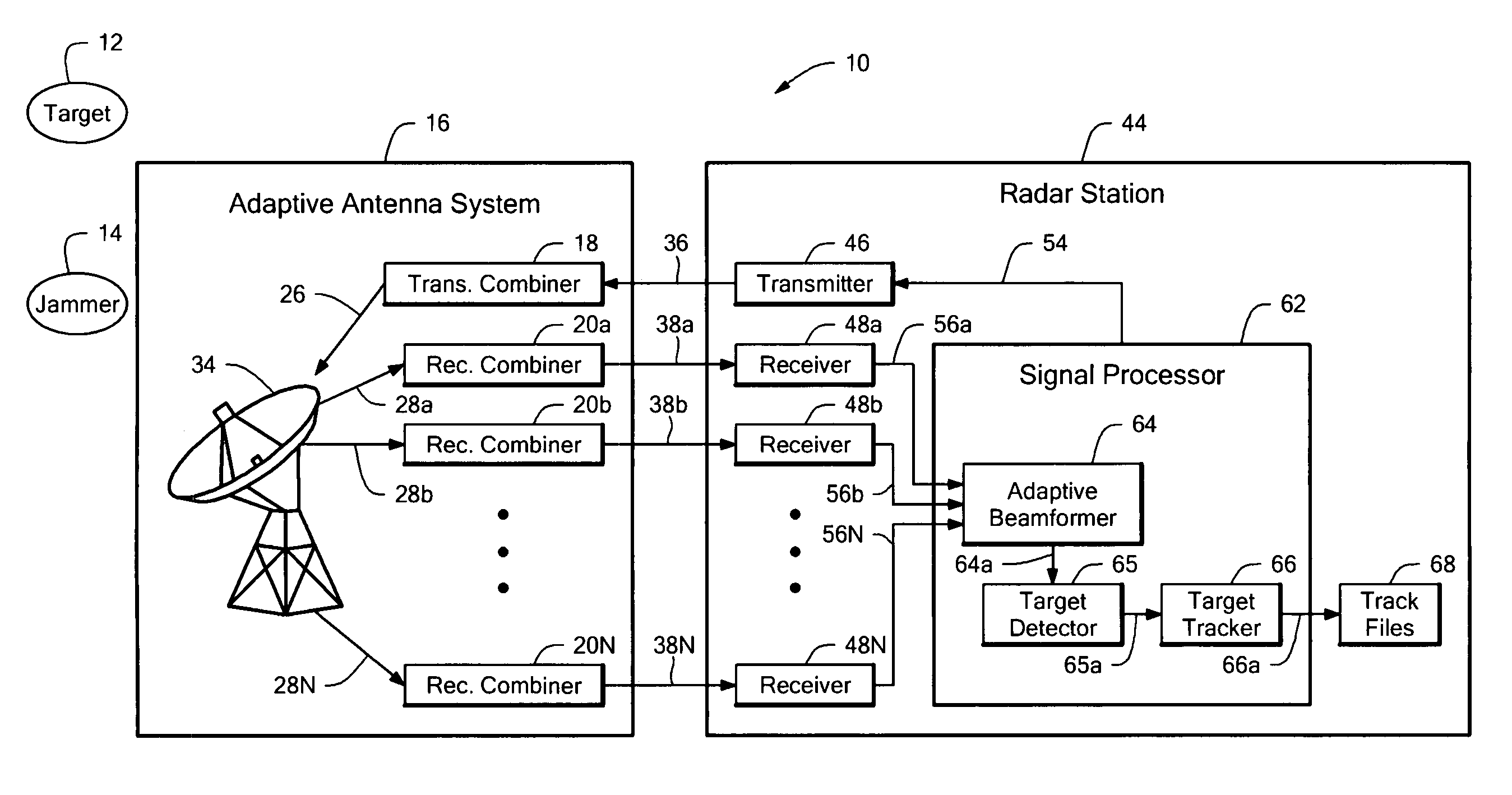
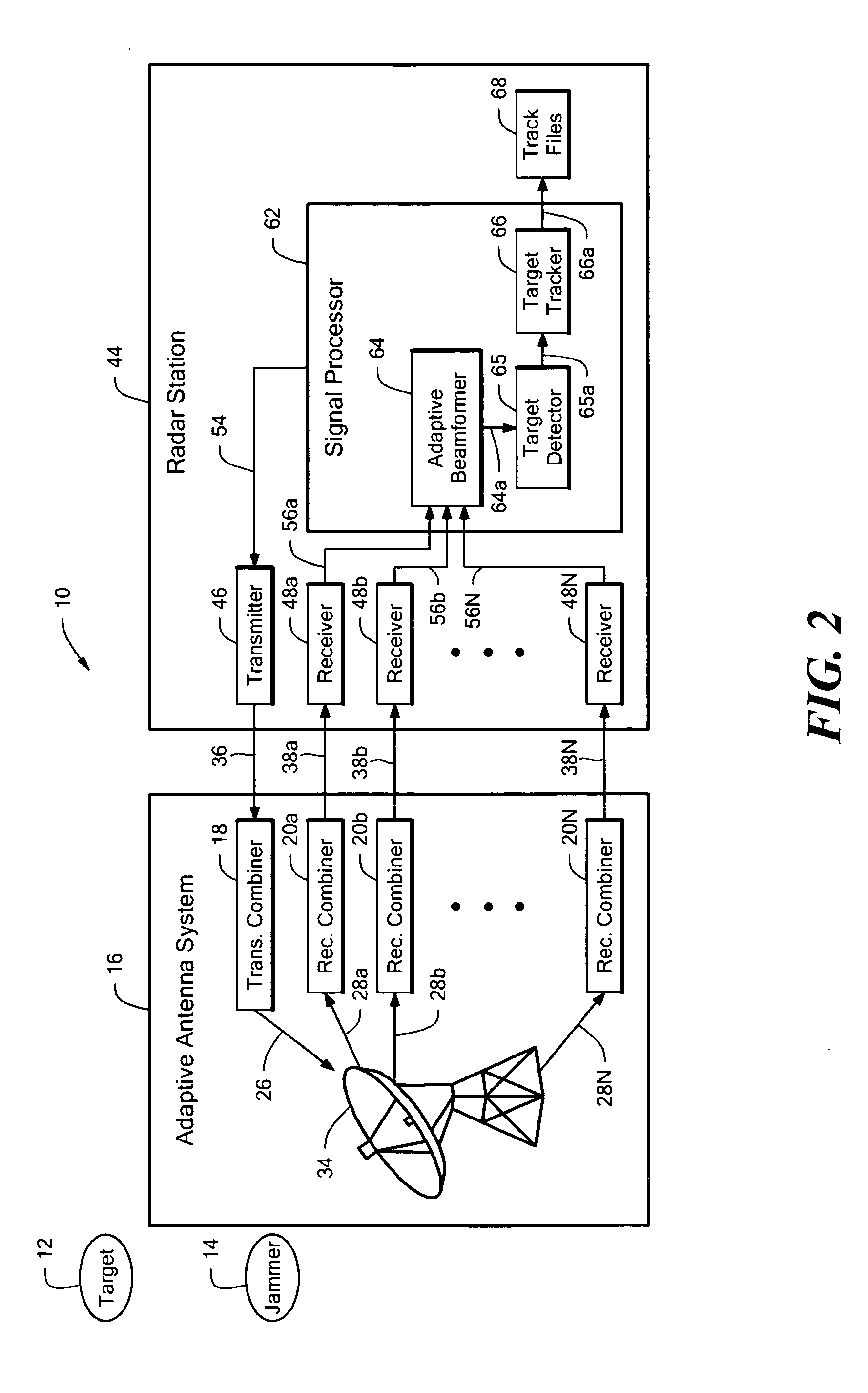
[0036] Referring to FIG. 2, an adaptive radar system 10 can be used in the presence of one or more targets, e.g., target 12, and one or more jammers, e.g., jammer 14. The adaptive radar system 10 includes an adaptive antenna system 16 coupled to a radar station 44. The adaptive antenna system 16 includes an adaptive antenna array 34 having subarrays (not shown). Each of the subarrays has elements (not shown) providing element outputs, for example, element outputs ...


PUM


Abstract

An adaptive antenna array has array elements arranged in element rows and element columns and subarrays arranged in subarray rows and subarray columns, for which the subarray phase centers have non-uniform spacing. The adaptive antenna array provides good detection and tracking performance when used in a radar system, while being inexpensive and easy to manufacture. A radar system and a method of adapting a radar array both employ the above described adaptive antenna array.

Description

STATEMENT REGARDING FEDERALLY SPONSORED RESEARCH [0001] This invention was made with government support under Contract No. DASG60-98-C-0001 awarded by the United States ARMY. The government has certain rights in the invention.CROSS REFERENCE TO RELATED APPLICATIONS [0002] Not Applicable. FIELD OF THE INVENTION [0003] This invention relates generally to radar arrays, and more particularly, to adaptive radar arrays. BACKGROUND OF THE INVENTION [0004] As is known, jammers emitting radar energy can degrade target detection and tracking performance of radar systems. The jammers can either be active jammers having the purpose of degrading radar performance, as in a battlefield, or the jammers can be non-combative radar emitters, for example, an aircraft in the vicinity of the radar system that has an on-board active radar system. [0005] Adaptive radar arrays are used in conjunction with adaptive beamforming within radar systems to reduce the impact of jammers on radar system detection and...

Claims


Application Information

Patent Timeline
Patent Type & Authority Applications(United States)
IPC IPC(8): G01S7/36
CPCG01S7/2813H01Q21/0025H01Q21/22
Inventor PAUPLIS, BARBARA E.SEGHEZZI, EDWARD A.CAREY, W. TIMOTHY
Owner RAYTHEON CO
Why Eureka
Try Eureka