Welding robot

a welding robot and robot body technology, applied in the field of welding robots, can solve the problems of ineffectiveness, defective welding, seam tracking, etc., and achieve the effect of high tracking ability and reliably preventing human error

Inactive Publication Date: 2009-07-16
KOBE STEEL LTD
View PDF12 Cites 42 Cited by
  • Summary
  • Abstract
  • Description
  • Claims
  • Application Information

AI Technical Summary

Benefits of technology

[0009]Accordingly, it is an object of the present invention to make it possible to, in a seam tracking operation during tandem welding, realize a high tracking ability, not only for a leading electrode, but also for a trailed electrode, and prevent human error without forcing an operator to perform a troublesome operation.
[0020]When the welding direction is changed by tracking, the controlling device including the rotation correction calculating means performs translational correction and a correction for rotating the torch around the leading electrode, to make it possible to achieve high tracking ability, not only for the leading electrode, but also for the trailed electrode. As a result, even when processing precision or setting precision of a weld object is low, or a dynamic error occurs during the welding due to, for example, thermal strain, it is possible to perform high-quality welding.
[0021]Since, by providing the leading electrode identifying means in the controlling device, the leading electrode is automatically identified, and the sensing unit corresponding to the leading electrode is automatically selected, an operator no longer needs to perform a troublesome operation in which the operator successively specifies a sensor that is used in a tracking control operation when forming a program as the operator does for a related welding robot. Therefore, it is possible to reliably prevent human error.

Problems solved by technology

Firstly, an adequate tracking ability cannot be ensured for, in particular, the trailed electrode. More specifically, defective welding occurs due to displacement of the trailed electrode after correcting a path by the tracking. As shown in FIG. 15, it is possible for an actual weld line Lre to be distorted with respect to a teaching path Lte, and for a travel direction of the torch 6, which is only corrected by a translational component, to have a rotational component with respect to a travel direction of the teaching path Lte. In this case, the leading electrode 5a correctly follows the actual weld line Lre, whereas the trailed electrode 5b is displaced from the actual weld line Lre by the positional displacement δ, thereby resulting in defective welding. The only way to overcome this problem is to reduce the correction amount resulting from the tracking. To reduce the correction amount resulting from the tracking, it is necessary, not only to increase the processing precision of a weld workpiece to be welded, but also to form a manufacturing surface so as to, for example, minimize welding thermal strain or positional displacement when setting the workpiece. Accordingly, seam tracking for essentially correcting these errors is not achieved effectively.
Secondly, the operation is troublesome to carry out, resulting in human errors. As mentioned above, in the related seam tracking operation, in determining whether or not an electrical current change of either one of the two arc electrodes is used in a tracking control, an operator specifies whether or not to use the electrical current change of either one of the two arc electrodes using, for example, a program command. However, in this method, when forming the program, the operator is forced to successively perform an input operation regarding which of the electrodes is to be selected while recognizing the welding direction. In addition, an improper tracking method in which tracking is performed on the basis of a change in current value of a trailed electrode when an input mistake is made may be selected.

Method used


Image

  • Welding robot
  • Welding robot
  • Welding robot

Examples


first embodiment (refer to fig.1)

First Embodiment (Refer to FIG. 1)

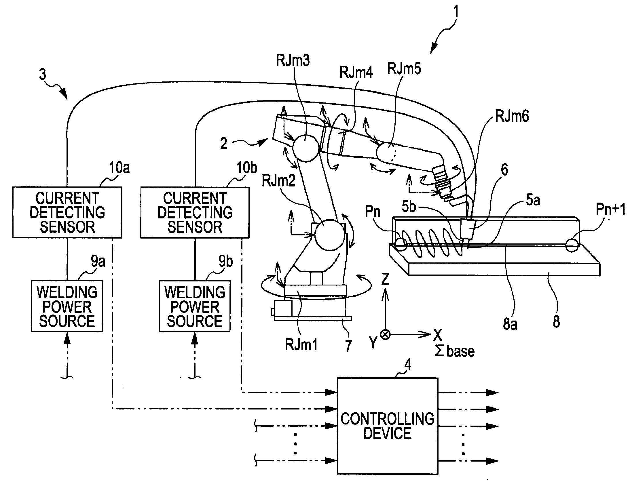
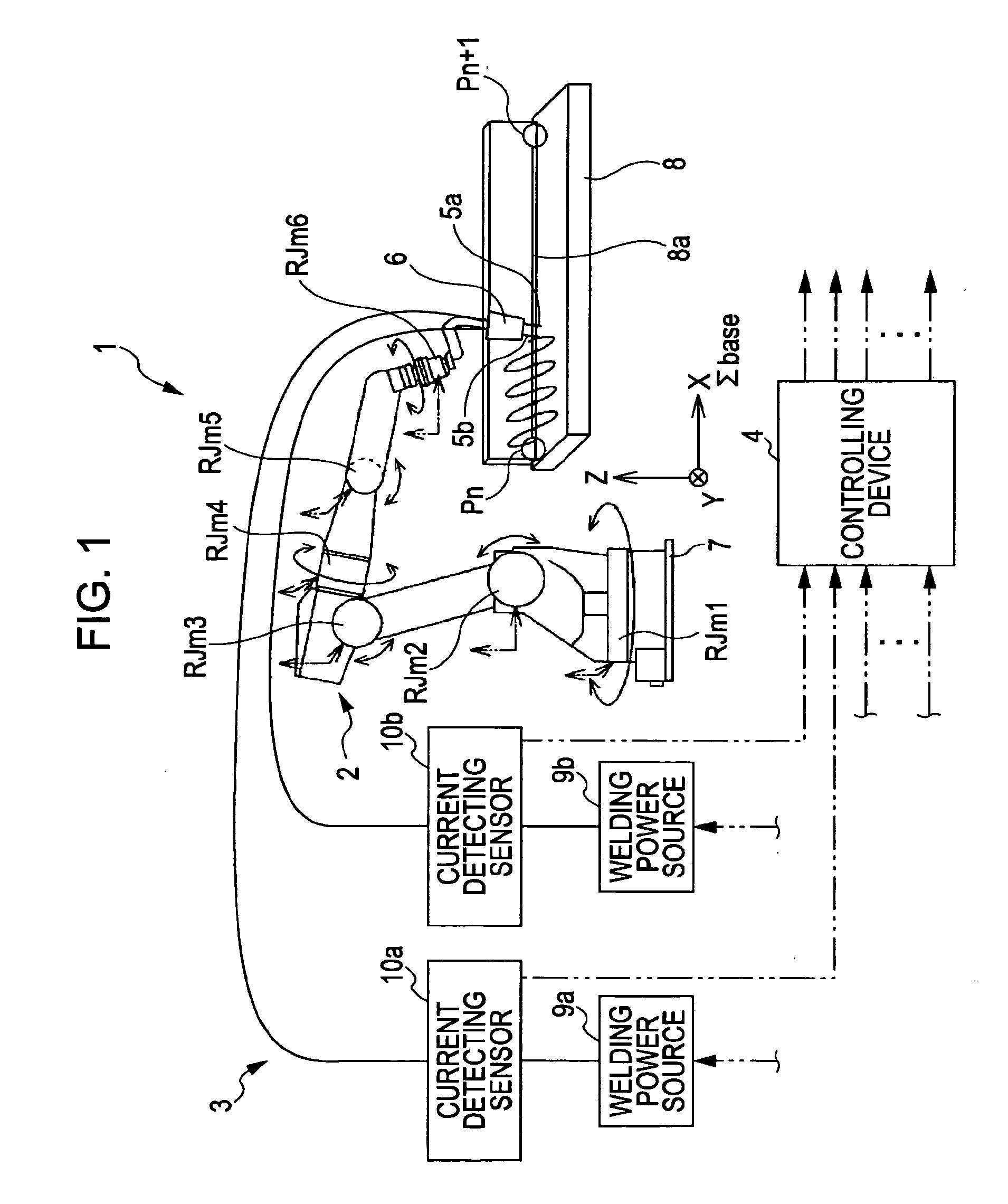
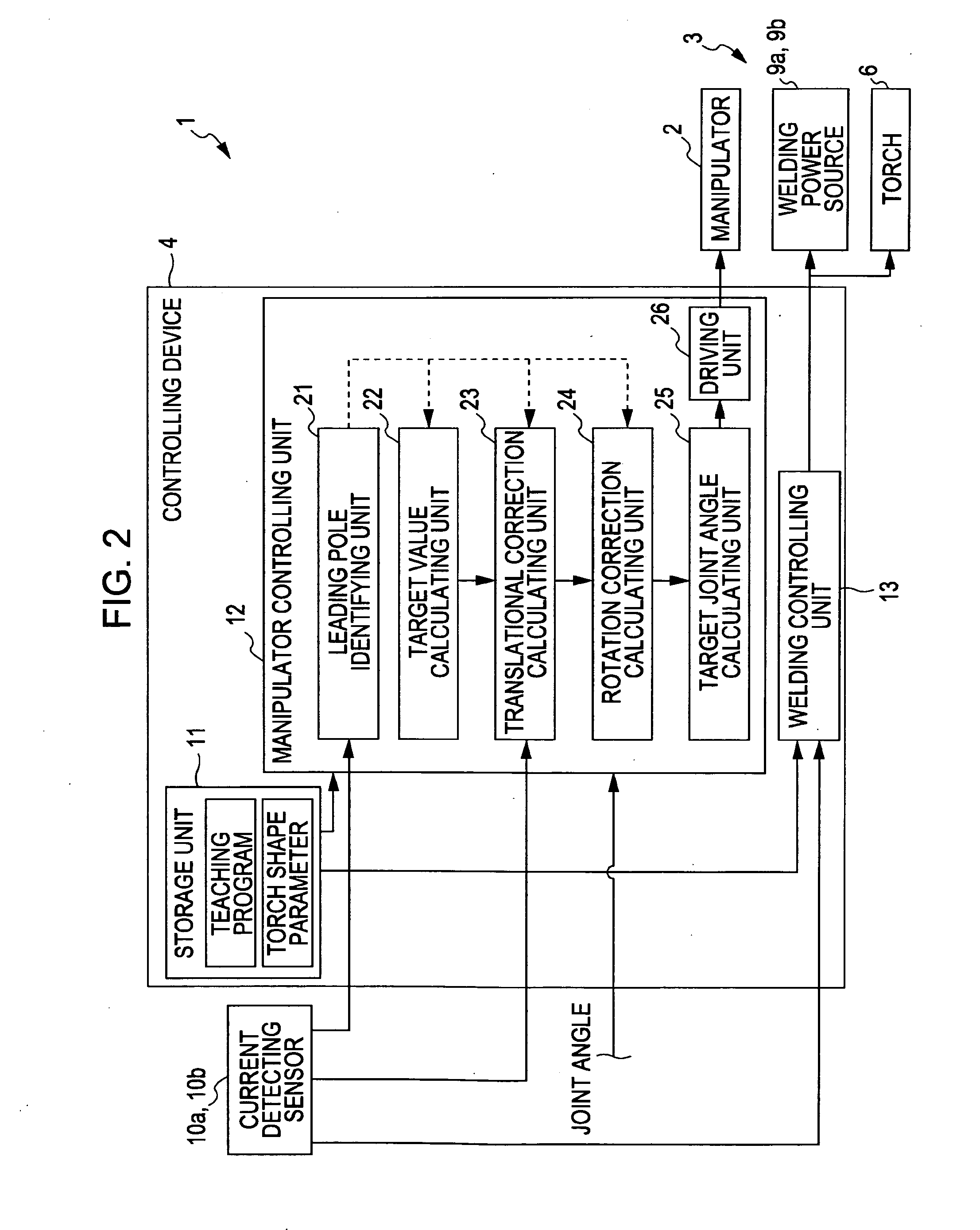
[0038]A welding robot 1 according to a first embodiment of the present invention shown in FIG. 1 comprises a manipulator 2, a welding unit 3, and a controlling device 4. The welding robot 1 automatically welds a workpiece (weld object) 8 along a weld joint 8a.

[0039]A tandem torch 6 having a pair of arc electrodes (hereafter simply referred to as “electrodes”), formed of wires, are mounted to a flange surface 2a (see FIG. 3) at an end of the manipulator 2. The manipulator 2 changes the position and the orientation of the torch 6 in three-dimensional space. The manipulator 2 has six rotational joints, RJm1, RJm2, RJm3, RJm4, RJm5, and RJm6. The rotational joints RJm1 to RJm6 are linked to each other with links, and the rotational joint RJm1 that is closest to a base end side is mounted to a base 7. The rotation joints RJm1 to RJm6 are provided with respective angle sensors for detecting motor joint angles J (J1, J2, J3, J4, J5, and J6) for rotational...

second embodiment (refer to fig.10)

Second Embodiment (Refer to FIG. 10)

[0080]A welding robot 1 according to a second embodiment of the present invention shown in FIGS. 10 and 11 comprises an optical sensor 100 instead of the current detecting sensors 10a and 10b (see FIGS. 1 and 2). The optical sensor 100 comprises a projector 101 and a light-receiving sensor 102. In the embodiment, the leading electrode is previously known (hereunder, an electrode 5a is the leading electrode).

[0081]Controlling operations (Steps S12-3 to S12-13) of a manipulator 2 executed by a controlling device 4 shown in FIG. 12 are similar to those in the first embodiment in that, after starting welding by moving a torch to a weld start position Pn (Steps S12-1 to S12-2), the following operations are repeated at every path calculation interval Tc, that is, calculation of a target value Plead(t) of the leading electrode 5a, calculation of a primary correction target value Plead(t) using a translational correction amount ΔP(t), calculation of a sec...


PUM

PropertyMeasurementUnit
positional displacementaaaaaaaaaa
joint angleaaaaaaaaaa
rotationaaaaaaaaaa

Abstract

A welding robot in which a translational correction calculating unit corrects a target value of a leading electrode using a translational correction amount, to obtain a primary correction target value. The translational correction amount is a correction amount of a position of the leading electrode in a translational direction in a base coordinate system at a next time. A rotational correction calculating unit calculates a rotation correction amount for correcting displacement of an orientation of a torch around the leading electrode with respect to a actual weld line, and calculates a secondary correction target value resulting from correcting the primary correction target value so that the torch rotates around the leading electrode by the rotation correction amount. The displacement is caused by the correction using the translational correction amount. A manipulator is driven on the basis of the secondary correction target value.

Description

BACKGROUND OF THE INVENTION[0001]1. Field of the Invention[0002]The present invention relates to a welding robot. More particularly, the present invention relates to a welding robot that performs seam tracking when performing tandem welding.[0003]2. Description of the Related Art[0004]In an automatic welding apparatus, such as a welding robot, seam tracking, in which a weld line is automatically followed using various sensors, is widely used. The purpose of seam tracking is to prevent defective welding, by detecting displacement of a weld target position with a sensor and by correcting the displacement. The displacement is caused by dynamic errors in a welding operation resulting from thermal strain, a setting error, or a processing error of a workpiece. FIG. 13 schematically shows the principle of seam tracking. A sensor 1 that is used may be, for example, a mechanical sensor, a sensor utilizing a change in arc-welding current, or an optical / visual sensor. Even if the type of senso...

Claims


Application Information

Patent Timeline
Patent Type & Authority Applications(United States)
IPC IPC(8): B23K9/00
CPCB23K9/1272B23K9/095B23K9/127B25J9/06B25J9/16
Inventor NISHIMURA, TOSHIHIKOSHIGEYOSHI, MASAYUKI
Owner KOBE STEEL LTD
Why Eureka
Try Eureka