Supercharge Your Innovation With Domain-Expert AI Agents!

Synchronous pulse power supply for millimeter wave solid-state power amplifier

A solid-state power amplifier and synchronous pulse technology, which is applied in the electronic field, can solve the problems of large power supply, only one channel, and extended output pulse falling edge time, and achieve the effect of small volume and small volume

Inactive Publication Date: 2017-03-22
SOUTHWEAT UNIV OF SCI & TECH
View PDF5 Cites 0 Cited by
  • Summary
  • Abstract
  • Description
  • Claims
  • Application Information

AI Technical Summary

Problems solved by technology

[0002] The traditional pulse power supply adopts a single-tube design output structure such as figure 1 As shown, the source of Mos tube Q1 is connected to the power supply VCC, and the drain is connected to the equivalent load to the ground level GND. The equivalent load includes resistor R1, parasitic capacitance C1 and parasitic inductance L1. The biggest disadvantage of this structure is that if the load is large Capacitive, the falling edge time of the output pulse will be extended, and the millimeter-wave solid-state power amplifier is just capacitive. This structure cannot meet the needs of the millimeter-wave solid-state power amplifier, and the traditional power supply drive control circuit is complex, the power supply is large, and often only has one channel , which is obviously not applicable to many occasions with volume limitations

Method used


Image

  • Synchronous pulse power supply for millimeter wave solid-state power amplifier
  • Synchronous pulse power supply for millimeter wave solid-state power amplifier
  • Synchronous pulse power supply for millimeter wave solid-state power amplifier

Examples


Embodiment Construction

[0021] Below in conjunction with accompanying drawing, the present invention is further described:

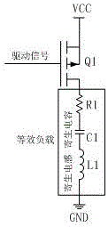
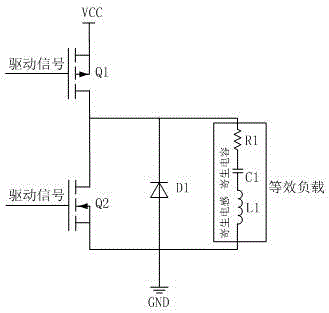
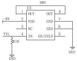
[0022] Overall structural block diagram of the present invention is as figure 2 As shown, a synchronous pulse power supply for a millimeter-wave solid-state power amplifier, the input is +8V and +28V DC power supply and TTL control signal level, the output is +8V and +28V pulse voltage signal, the two pulse power supplies are independent of each other, respectively have The Mos tube drive circuit, output edge adjustment circuit, and modulation switch circuit required for modulating the voltage are Mos tube drive circuit 1, output edge adjustment circuit 1, modulation switch circuit 1 and Mos tube drive circuit 2, output edge adjustment circuit 2, and modulation switch Circuit 2, +8V DC power supply to Mos tube drive circuit 1, output edge regulation circuit 1, modulation switch circuit 1, and input 0~+5V TTL control signal level to Mos tube drive circuit 1, Mos tube drive circ...


PUM


Abstract

The invention discloses a synchronous pulse power supply for a millimeter wave solid-state power amplifier. The input is +8V and +28V direct current power and TTL control signal level, and the output is +8V and +28V pulse voltage signals; the synchronous pulse power supply comprises an Mos transistor driving circuit, an output edge adjusting circuit and a modulation switch circuit; the Mos transistor driving circuit generates complementary Mos transistor driving control signals, the output edge adjusting circuit can adjust the rising edge and falling edge time of the output end of the pulse power supply, the modulation switch circuit is a complementary common-source push-pull output circuit composed of a P channel MOS transistor and an N channel MOS transistor, and the pulse power supply for the millimeter wave solid-state power amplifier is an indispensable component of the millimeter wave solid-state power amplifier as a driving source. By adopting a push-pull structure, the synchronous pulse power supply meets the requirement for capacitive load characteristic of the millimeter wave synthetic power amplifier, overcomes the defect of poor capacitive load characteristic of a single-tube power supply design, solves the problem of adjustability of the output edge and improves the reliability.

Description

technical field [0001] The invention relates to the field of electronic technology, in particular to a synchronous pulse power supply for a millimeter-wave solid-state power amplifier. Background technique [0002] The traditional pulse power supply adopts a single-tube design output structure such as figure 1 As shown, the source of Mos tube Q1 is connected to the power supply VCC, and the drain is connected to the equivalent load to the ground level GND. The equivalent load includes resistor R1, parasitic capacitance C1 and parasitic inductance L1. The biggest disadvantage of this structure is that if the load is large Capacitive, the falling edge time of the output pulse will be extended, and the millimeter-wave solid-state power amplifier is just capacitive. This structure cannot meet the needs of the millimeter-wave solid-state power amplifier, and the traditional power supply drive control circuit is complex, the power supply is large, and often only has one channel ,...

Claims


Application Information

Patent Timeline
Patent Type & Authority Applications(China)
IPC IPC(8): H02M9/02H02M1/08
CPCH02M1/08H02M11/00
Inventor 朱玉玉武丽王静陈锐
Owner SOUTHWEAT UNIV OF SCI & TECH
Features
  • R&D
  • Intellectual Property
  • Life Sciences
  • Materials
  • Tech Scout
  • Unparalleled Data Quality
  • Higher Quality Content
  • 60% Fewer Hallucinations
Learn More