Method for detecting, controlling and automatically compensating pressure in polishing process

An automatic compensation and pressure technology, which is applied in the direction of program control, electrical program control, workpiece feed movement control, etc., to achieve the effect of maintaining stable pressure, satisfying high precision and ensuring quality

Active Publication Date: 2017-04-05
TUNG HING AUTOMATION INVESTMENT LTD +1
View PDF7 Cites 19 Cited by
  • Summary
  • Abstract
  • Description
  • Claims
  • Application Information

AI Technical Summary

Problems solved by technology
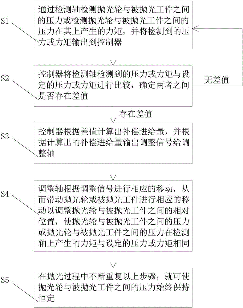
[0008] The purpose of the present invention is to overcome the helplessness and inability of the above-mentioned manpower and the deficiency of the prior art, and provide a method for pressure detection, control and automatic compensation in the polishing process, which can realize the pressure detection and control between the grinding wheel and the workpiece during the polishing process And automatic compensation, to meet the requirements of precision, stable and consistent processing quality, and high-efficiency operation

Method used


Image

  • Method for detecting, controlling and automatically compensating pressure in polishing process
  • Method for detecting, controlling and automatically compensating pressure in polishing process
  • Method for detecting, controlling and automatically compensating pressure in polishing process

Examples


no. 1 example

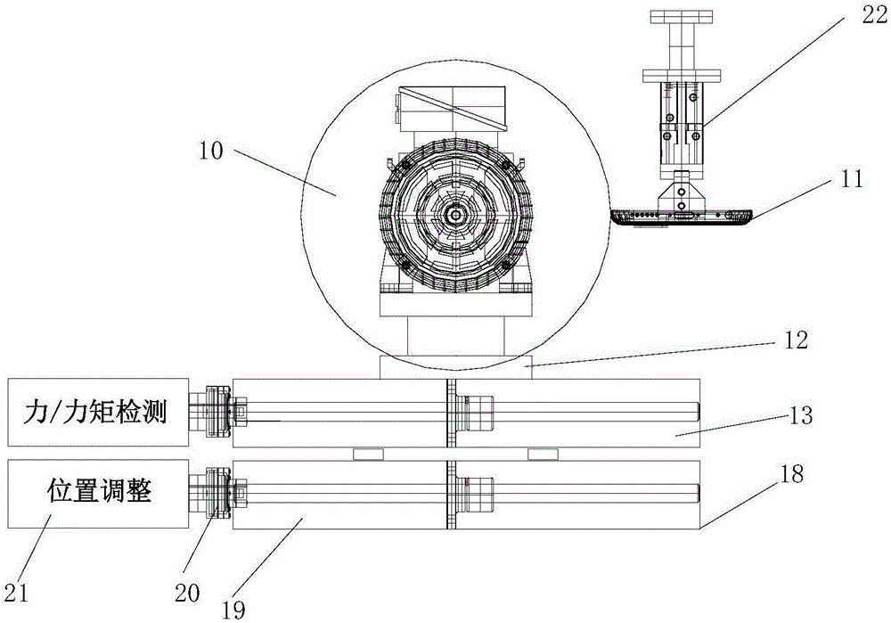
[0050] refer to figure 2 , in this embodiment, the substrate 12 of the polishing wheel 10 is fixed to the detection shaft 13, so that the center of the detection shaft 13 is located on the same vertical line as the center of the substrate 12, and is located on the same vertical line as the center of the polishing wheel 10. In-plane, that is, fixing the polishing wheel 10 to the test shaft. The polishing wheel 10 may be a grinding wheel. Fix the polished workpiece 11 to the polishing station 22 so that the center of the polished workpiece 11 and the center of the polishing wheel 10 are on the same horizontal line. The adjustment shaft 18 is fixed to the detection shaft 13 . The adjustment shaft 18 includes a main body 19 , a coupling 20 disposed on the main body 19 and a driver 21 fixed to the coupling 20 . The driver 21 receives an adjustment signal output by the controller and drives the main body 19 to move accordingly.

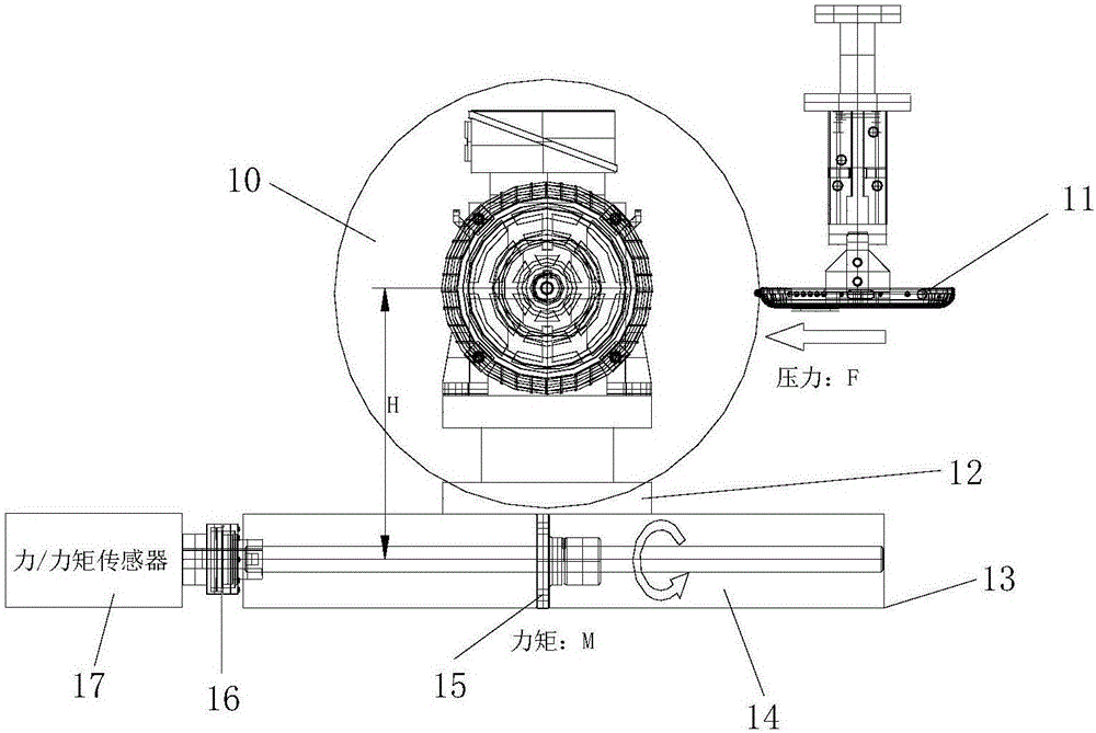
[0051] refer to image 3 , The detection shaft 1...

no. 2 example

[0058] In this example, refer to Figure 6 , different from the first embodiment, the polishing station 22 is fixed to the adjustment shaft 18 , that is, the workpiece 11 to be polished is fixed to the adjustment shaft 18 . The difference values ​​determined by the controller are respectively described with examples below as positive difference values ​​and negative difference values.

[0059] Still take the detection shaft 13 to detect the torque generated by the pressure between the polishing wheel 10 and the workpiece 11 to be polished as an example, assuming that the set torque M0 is 5%, the polishing wheel 10 and the workpiece 11 to be polished are not in contact with each other. The pressure F between them is 0, according to the pressure F=0, the pressure F between the polishing wheel 10 detected by the detection shaft 13 and the workpiece 11 to be polished produces a torque M1 on it that is 0, and the controller detects the detection shaft 13 The received torque M1 is ...

no. 3 example

[0062] refer to Figure 7 , unlike the first embodiment, the base plate 12 of the polishing wheel 10 is fixed to the adjustment shaft 18 , ie the polishing wheel 10 is fixed to the adjustment shaft 18 . The polishing station 22 is fixed to the detection axis 13 , that is, the polished workpiece 11 is fixed to the detection axis 13 . The center of the polished workpiece 11 and the center of the detection axis 13 are located in the same vertical plane. The detection shaft 13 detects the pressure or torque between the polishing wheel 10 and the workpiece 11 to be polished in the same principle as the first embodiment, which will not be repeated here. The difference values ​​determined by the controller are respectively described with examples below as positive difference values ​​and negative difference values.

[0063]Still take the detection shaft 13 to detect the torque generated by the pressure between the polishing wheel 10 and the workpiece 11 to be polished as an example...


PUM


Abstract

The invention relates to a method for detecting, controlling and automatically compensating pressure in a polishing process. The method comprises the following steps: a detection shaft detects pressure between a polishing wheel and a polished workpiece or a torque generated on the polished workpiece based on the pressure, and outputs the detected pressure or torque to a controller; the controller compares the pressure or torque detected by the detection shaft with set pressure or torque to determine whether a difference value exists between the detected pressure or torque and the set pressure or torque, and if no difference value exists, the last step is repeated, or if the difference value exists, the next step is carried out; the controller calculates a compensation feeding amount according to the difference value and outputs an adjustment signal to an adjustment shaft according to the compensation feeding amount; and the adjustment shaft correspondingly moves according to the adjustment signal so as to drive the polishing wheel or the polished workpiece to move correspondingly to adjust a relative position between the polishing wheel and the polished workpiece to enable the difference value to trend to be and keep consistent. According to the method disclosed by the invention, the pressure between the polishing wheel and the polished workpiece in the polishing process can be kept constant, and stability and consistency of the machining quality of the polished workpiece are guaranteed.

Description

[0001] 【Technical field】 [0002] The invention relates to a method for pressure detection, control and automatic compensation of polishing equipment during the polishing process. [0003] 【Background technique】 [0004] In the manufacturing process, there is a large demand for the polishing of workpieces, ranging from aerospace parts, automobile molds, to a small decorative part, including military products, industrial products, and civilian products. During the polishing process, the factors that affect the processing quality are: the direct pressure between the grinding wheel and the workpiece, the running speed when the grinding wheel is in contact with the workpiece, the material properties of the grinding wheel and the workpiece, the processing process and appropriate process parameters, and the consistency of the original workpiece , and the stability of processing equipment, etc. Obviously, the main key is to keep the direct pressure between the grinding wheel and the ...

Claims


Application Information

Patent Timeline
Patent Type & Authority Applications(China)
IPC IPC(8): B24B49/00
CPCB24B49/00B24B49/16G05B19/18G05B2219/45161G05B2219/45199
Inventor 陈永强
Owner TUNG HING AUTOMATION INVESTMENT LTD
Why Eureka
Try Eureka