
An intelligent stamping device for industrial production

A kind of equipment and intelligent technology, applied in the direction of stamping, printing, etc., can solve the problems of increasing the loss of the push rod, reducing the service life of the equipment, noise, etc., to achieve the effect of improving reliability and service life, smooth transmission and noise, and improving reliability

Active Publication Date: 2018-10-23
凤阳聚梦信息科技有限责任公司
View PDF20 Cites 0 Cited by
  • Summary
  • Abstract
  • Description
  • Claims
  • Application Information

AI Technical Summary

Problems solved by technology

[0003] In the existing stamping equipment, when stamping the surface of the product, it is necessary to control the up and down movement of the stamp to ensure that the products that come in sequence are stamped, but in the mechanism for controlling the stamp, generally The mechanical mechanism of gear transmission can not control the stability of the engraving movement well, and it also has a lot of noise, which greatly reduces the practicability of the equipment; not only that, when moving the product, due to the The limit method of the push rod is the sliding limit method, which greatly improves the sliding coefficient between the push rod and the limit rod, increases the loss of the push rod, and reduces the service life of the equipment

Method used


Image

  • An intelligent stamping device for industrial production
  • An intelligent stamping device for industrial production
  • An intelligent stamping device for industrial production

Examples


Embodiment Construction

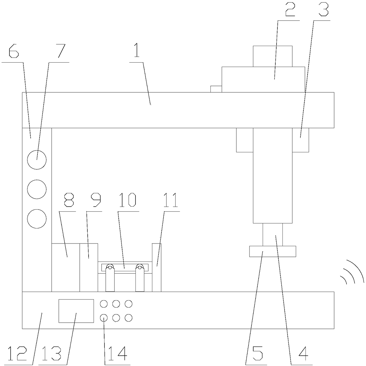
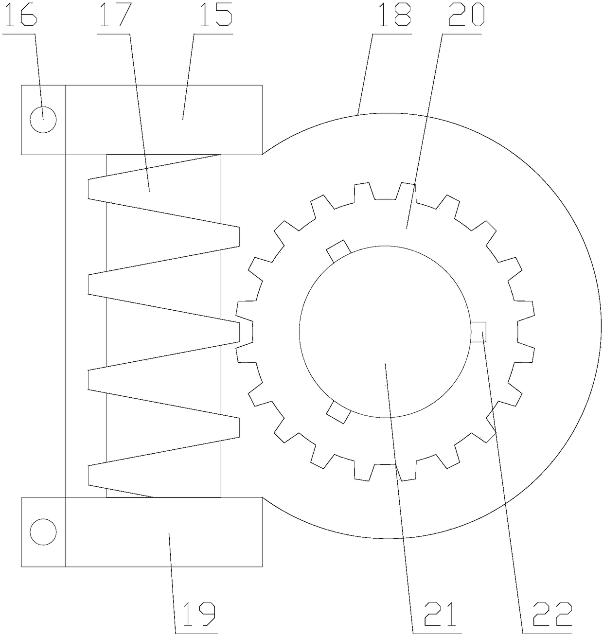
[0028] The present invention is described in further detail now in conjunction with accompanying drawing. These drawings are all simplified schematic diagrams, which only illustrate the basic structure of the present invention in a schematic manner, so they only show the configurations related to the present invention.

[0029] like Figure 1-Figure 6 As shown, an intelligent stamping device for industrial production includes a base 12, a column 6 arranged on one side of the base 12, a beam 1 arranged at the top of the column 6, and a stamping mechanism arranged on the base 12 ;

[0030] Described affixing mechanism comprises moving assembly 2 and affixing assembly, and described moving assembly 2 is arranged on one side of affixing assembly, and described affixing assembly comprises lift drive assembly and is arranged on the seal unit below lift drive assembly, so The lifting drive assembly includes a drive unit and a transmission unit, and the drive unit includes a first m...


PUM


Abstract

The invention relates to intelligent stamping equipment for industrial production. The intelligent stamping equipment for industrial production comprises a base, an upright column, a cross beam and a stamping mechanism, wherein the upright column is arranged on one side of the base; the cross beam is arranged at the top end of the upright column; the stamping mechanism is arranged on the base; the stamping mechanism comprises a moving assembly and a stamping assembly; a transmission gear is driven by a worm and a lifting rod rotates along with the transmission gear; the lifting rod is provided with external threads and the inner side of a through hole in the cross beam is provided with internal threads, so ascending and descending of the lifting rod can be realized, the effects of stable transmission and noise reduction can be achieved and the working reliability of the equipment is improved; moreover, in a stretching assembly, a rolling wheel can roll in a limiting guide rail on a pushing rod in the horizontal movement process of the pushing rod, so that rolling connection of the pushing rod and a limiting unit is realized, the limiting reliability is improved and the service life is prolonged.

Description

technical field [0001] The invention relates to an intelligent stamping device for industrial production. Background technique [0002] Stamping equipment is the equipment for stamping on products. [0003] In the existing stamping equipment, when stamping the surface of the product, it is necessary to control the up and down movement of the stamp to ensure that the products that come in sequence are stamped, but in the mechanism for controlling the stamp, generally The mechanical mechanism of gear transmission can not control the stability of the engraving movement well, and it also has a lot of noise, which greatly reduces the practicability of the equipment; not only that, when moving the product, due to the The position limiting method of the push rod adopts the sliding limit mode, which greatly improves the sliding coefficient between the push rod and the limit rod, improves the loss of the push rod, and reduces the service life of the equipment. Contents of the inve...

Claims


Application Information

Patent Timeline
Patent Type & Authority Patents(China)
IPC IPC(8): B41K3/04B41K3/62
CPCB41K3/04B41K3/62
Inventor 齐进才
Owner 凤阳聚梦信息科技有限责任公司
Learn More