
Frequency Converter and Its Frequency Given Signal Fault Detection Method
A technology of given signal and frequency converter, applied in the field of frequency converter control, can solve the problem of frequency signal failure of frequency converter, which cannot be detected in time.
- Summary
- Abstract
- Description
- Claims
- Application Information
AI Technical Summary
Problems solved by technology
Method used
Image

Examples
Embodiment Construction
[0016] The following describes the present invention clearly and completely in conjunction with the technical solutions of the embodiments of the present invention. Obviously, the described embodiments are only a part of the embodiments of the present invention, rather than all the embodiments. Based on the embodiments of the present invention, all other embodiments obtained by those of ordinary skill in the art without creative work shall fall within the protection scope of the present invention.
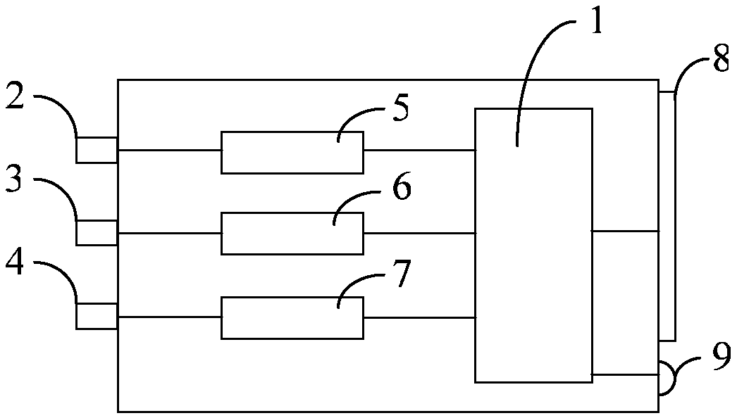
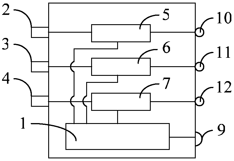
[0017] The frequency converter of the first embodiment of the present invention is such as figure 1 As shown, it includes a control unit 1, a rising signal terminal 2 and a falling signal terminal 3. The rising signal terminal 2 and the falling signal terminal 3 are respectively connected to the rising signal monitoring terminal 5 and the falling signal monitoring terminal 6 inside the inverter. Both the rising signal monitoring terminal 5 and the falling signal monitoring terminal 6 a...
PUM
 Abstract
Description
Claims
Application Information