
Spring drive device for three-position switching operating mechanism

An operating mechanism and spring-driven technology, applied to the power device inside the switch, contact operating mechanism, electric switch, etc., to achieve the effects of facilitating production organization, simple and practical operation, and improving work efficiency

Inactive Publication Date: 2017-04-19
BEIHAI GALAXY SWITCH DEVICES
View PDF7 Cites 6 Cited by
  • Summary
  • Abstract
  • Description
  • Claims
  • Application Information

AI Technical Summary

Problems solved by technology

[0003] The purpose of the present invention is to provide a spring driving device for a three-position switch operating mechanism, which solves the problem of miniaturization of the spring driving mechanism and the problem of automatic reverse energy storage

Method used


Image

  • Spring drive device for three-position switching operating mechanism
  • Spring drive device for three-position switching operating mechanism
  • Spring drive device for three-position switching operating mechanism

Examples


Embodiment 1

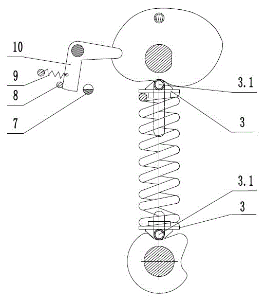
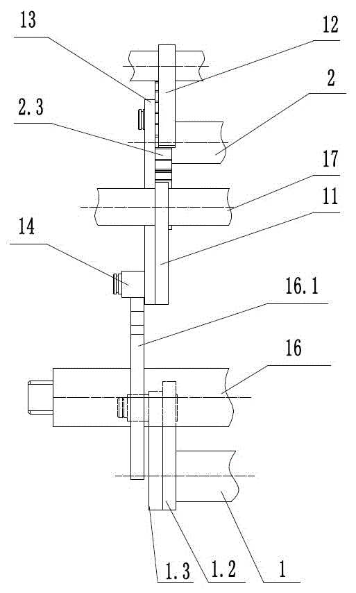
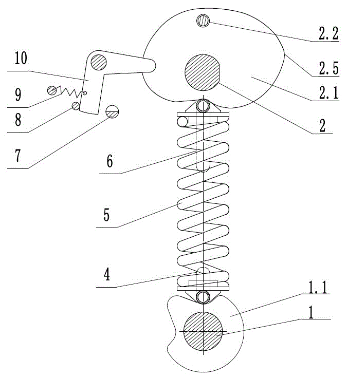
[0023] Embodiment 1: A spring driving device of a three-position switch operating mechanism, including a front plate, a middle plate, a rear plate and its support column for fixing and supporting, a grounding operation shaft 1, a switch operation shaft 2, and an output shaft 16 runs through the front plate, the middle plate and the rear plate, and the rotating shaft 17 is fixed on the middle plate. The switch operation shaft 2 and the grounding operation shaft 1 are vertically distributed, the closing spring 5 is located in the middle of the switch operation shaft 2 and the grounding operation shaft 1, and the grounding operation shaft 1 is provided with two grounding devices located symmetrically between the front plate and the middle plate. Cam 1.1, driving plate 1.2 and driving crank arm 1.3 located between the middle plate and the rear plate, two closing cams 2.1, cam rollers 2.2 and ratchets arranged symmetrically between the front plate and the middle plate on the switch ...

Embodiment 2

[0025] Embodiment 2: The hanging spring arm 1.5 replaces the grounding cam 1.1, the grounding limit block 19 and the opening limit block 18 replace the two grooves on the grounding cam 1.1, and the hanging spring seat 20 replaces the spring seat connected to the grounding cam 1.1 3. The shaft pin 21 replaces the spring seat roller 3.1 to realize the grounding and opening operation of the grounding switch. The hanging spring seat 20 is connected with the hanging spring crank arm 1.5 by a pivot pin 21. All the other are with embodiment 1.


PUM


Abstract

The invention relates to the technical field of power switch equipment, especially a spring drive device for a three-position switching operating mechanism. Aiming at a problem that a space is needed for the swinging amplitude of a spring and the telescoping motion of the spring because a spring device of a conventional three-position switching operating mechanism is disposed on a connecting lever of an operating shaft and a drive shaft and the spring passes through the connecting lever to form inclined angles with the drive shaft and the operating shaft, and a problem of miniaturization difficulty caused by that the size of the connecting lever cannot be too small because of the limiting of a drive moment, the device employs a mode that the spring drives a cam to move. The axis of a switching-on spring, the axis of a grounding operating shaft, the axis of a switching operating shaft, the axis of a spring seat roller and the axis of a guide groove are enabled to be collinear, thereby enabling the spring to just move up and down and not to swing, solving a problem that the space occupied by the spring is too big, remarkably reducing the size of an operating mechanism, and enabling the device to be simpler and more practical.

Description

technical field [0001] The invention relates to the technical field of electric switchgear, in particular to a spring driving device of a three-position switch operating mechanism. Background technique [0002] Using a spring energy storage operating mechanism to realize the opening and closing operation of the switchgear is a common method in the switchgear at present. Publication numbers CN103035424A and CN103021721A have introduced commonly used switch spring operating mechanisms. The above-mentioned patent documents disclose that one end of the energy storage spring is fixed to the operating shaft through the crank arm, and the other end is fixed to the drive shaft through the crank arm, the compression spring is driven through the operating shaft, and then the drive shaft is driven to rotate clockwise or counterclockwise through the release spring to realize the three-way operation. There are three working states of conduction, isolation and grounding of the position l...

Claims


Application Information

Patent Timeline
Patent Type & Authority Applications(China)
IPC IPC(8): H01H3/30
CPCH01H3/3015H01H3/3047
Inventor 刘桂华周振业董淑春邱宇
Owner BEIHAI GALAXY SWITCH DEVICES
Learn More