Insulating shoe sole

A bottom surface and body technology, applied in the field of insulated shoe soles, can solve the problems of poor versatility and inconvenient wearing of insulated shoes, and achieve the effect of solving inconvenient wearing

Inactive Publication Date: 2017-04-26
STATE GRID BEIJING ELECTRIC POWER +1
View PDF5 Cites 0 Cited by
  • Summary
  • Abstract
  • Description
  • Claims
  • Application Information

AI Technical Summary

Problems solved by technology

[0004] The main purpose of the present invention is to provide an insulating shoe sole to solve the problems of inconvenient wearing and poor versatility of insulating shoes in the prior art

Method used


Image

  • Insulating shoe sole

Examples


Embodiment 2

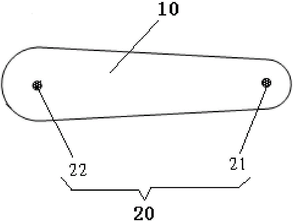
[0029] The insulating shoe sole of the second embodiment includes: a shoe sole body 10 , a locking part and a potential detection component 20 . The locking portion is disposed on the side of the sole body 10 . The potential detection assembly 20 comprises a first contact 21, a second contact 22 and an alarm unit, the first contact 21, the second contact 22 and the alarm unit are connected by wires, the alarm unit is arranged on the sole body 10, the first The contact 21 and the second contact 22 are spaced apart on the bottom surface of the sole body 10, so that the first contact 21 and the second contact 22 can contact the ground when the sole body 10 touches the ground.

Embodiment 3

[0036] The difference between the insulating sole of the third embodiment and the first embodiment is that the alarm unit includes a vibrator, and the vibrator is arranged on the sole body 10 . In this way, the operator can feel the existence of danger through the vibration of the operator.

[0037]The insulating shoe sole of the third embodiment includes: a shoe sole body 10 , a locking part and a potential detection component 20 . The locking portion is disposed on the side of the sole body 10 . The potential detection assembly 20 comprises a first contact 21, a second contact 22 and an alarm unit, the first contact 21, the second contact 22 and the alarm unit are connected by wires, the alarm unit is arranged on the sole body 10, the first The contact 21 and the second contact 22 are spaced apart on the bottom surface of the sole body 10, so that the first contact 21 and the second contact 22 can contact the ground when the sole body 10 touches the ground.


PUM


Abstract

The invention provides an insulating shoe sole. The shoe sole comprises a sole body, a clamping part which is arranged on the lateral side of the sole body and an electric potential detection component, wherein the electric potential detection component comprises a first contact, a second contact and an alarm unit, wherein the first contact, the second contact and the alarm unit are communicated through lead wires; the alarm unit is arranged on the sole body; the first contact and the second contact are alternately arranged at the bottom of the sole body, so that the first contact and the second contact can be contacted with the ground when the sole body is contacted with the ground. According to the technical scheme, the problems of wearing inconvenience and weak universality of insulating shoes in the prior art can be effectively solved.

Description

technical field [0001] The invention relates to the technical field of insulating shoe soles, in particular to an insulating shoe sole. Background technique [0002] When a ground fault occurs in the power supply equipment, different potential distributions will be formed on the ground around the ground point. When a person walking near the ground point walks into the short-circuit point, the potential difference between the two feet is called step voltage. When a charged wire breaks and falls on the ground, the potential of the landing point is the same as that of the wire, and the current will flow from the landing point of the wire to the ground. Therefore, a potential distribution area is formed on the ground centered on the landing point of the wire. The farther the current is, the more dispersed the current is, and the lower the ground potential is. If a person stands within a certain range from the landing point of the electric wire, an electric shock accident may oc...

Claims


Application Information

Patent Timeline
Patent Type & Authority Applications(China)
IPC IPC(8): A43B13/22A43B13/00
CPCA43B13/22A43B13/00
Inventor 宫译淳栗树材李清涛赵新历钱旭东赵小光
Owner STATE GRID BEIJING ELECTRIC POWER
Why Eureka
Try Eureka