A Parallel Robot Mechanism Realizing Scara Motion

A robot and parallel technology, applied in manipulators, program-controlled manipulators, manufacturing tools, etc., can solve the problems of unfavorable mechanism dynamic response characteristics, easy to generate vibration, etc., to improve stiffness and dynamic response characteristics, simple and compact mechanism, and realize high-speed and The effect of high acceleration

Active Publication Date: 2018-11-13
江苏小野智能装备有限公司
View PDF2 Cites 0 Cited by
  • Summary
  • Abstract
  • Description
  • Claims
  • Application Information

AI Technical Summary

Problems solved by technology

However, the limitation of the above-mentioned mechanism is that: there is no supporting connecting piece between the remote frame rods, which is prone to vibration, which is not conducive to improving the dynamic response characteristics of the mechanism

Method used


Image

  • A Parallel Robot Mechanism Realizing Scara Motion
  • A Parallel Robot Mechanism Realizing Scara Motion
  • A Parallel Robot Mechanism Realizing Scara Motion

Examples


Embodiment 1

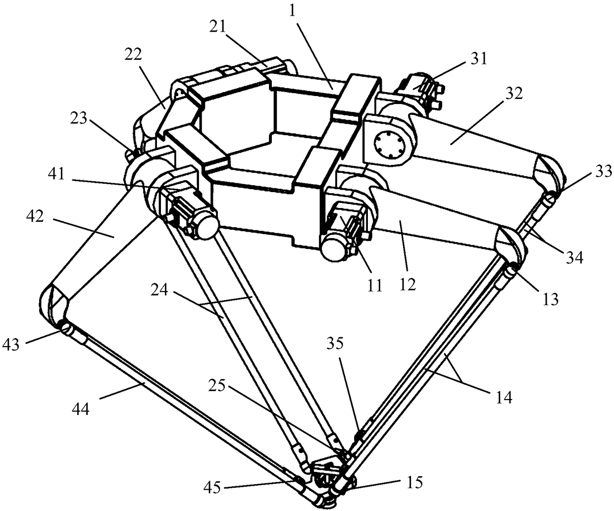
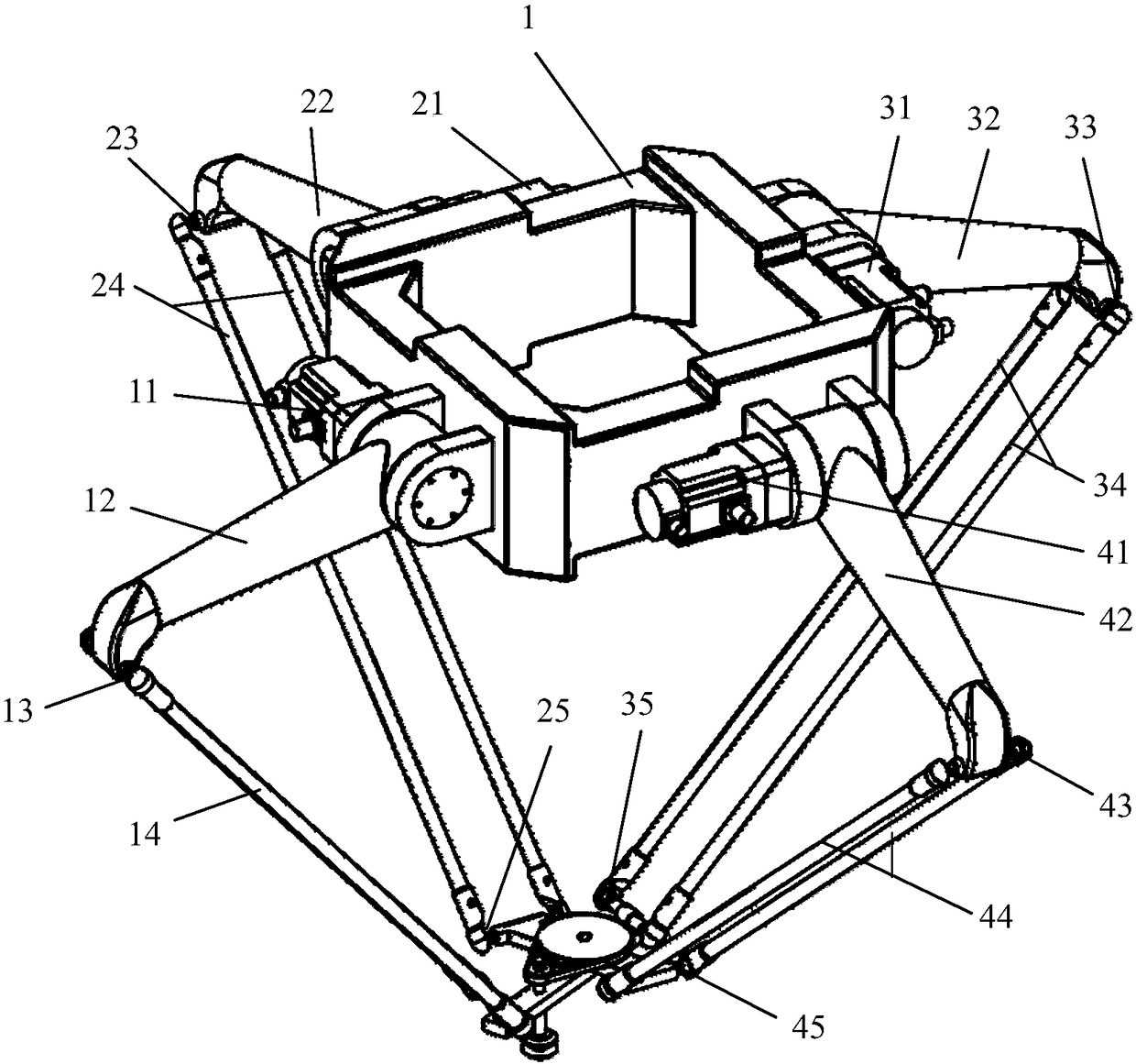
[0037] combined with Figure 1-2 , a parallel robot mechanism that can realize SCARA motion, including a fixed frame 1, a moving platform, and a first branch chain, a second branch chain, a third branch chain and a fourth branch chain arranged between the fixed frame 1 and the moving platform , taking the first branch chain as an example, the four branch chains all include a driving device 11, a near frame rod 12, an upper connecting shaft 13, a lower connecting shaft 15, two parallel and equal long far frame rods 14, and the driving The device 11 is fixedly connected with the fixed frame 1, and one end of the near frame rod 12 is rotationally connected with the fixed frame 1, and is fixedly connected with the driving end of the driving device 11, and the other end is fixedly connected with an upper connecting shaft 13, and the far frame rod One end of 14 is ball-hinged with upper connecting shaft 13, and the other end of said remote frame rod 14 is ball-hinged with lower conn...

Embodiment 2

[0044] combined with Figure 3-4 , this embodiment is similar to embodiment 1, the difference is only in:

[0045] The first branch chain and the third branch chain are oppositely arranged.

[0046] A large pulley 103 is fixedly connected to the auxiliary platform 5; a small pulley 101 is connected to the main platform 2; the small pulley 101 and the large pulley 103 are connected by a belt 102; the small belt The end effector 10 is fixedly connected to the lower end of the wheel 101 . The central axis of the large pulley 103 is coaxial with the rotation axis connecting the main platform 2 and the auxiliary platform 5 .

Embodiment 3

[0048] combined with Figure 5-6 , this embodiment is similar to embodiment 2, the only difference is:

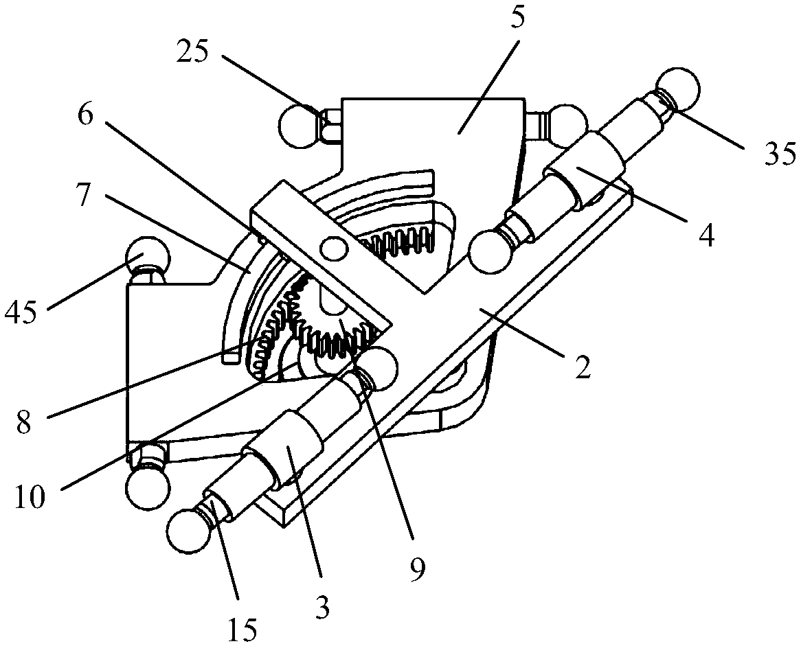
[0049] A large toothed fan 104 is fixedly connected to the auxiliary platform 5; a pinion 9 is connected to the main platform 2; the small gear 9 meshes with the large toothed fan 104; an end effector is fixedly connected to the lower end of the small gear . The central axis of the large tooth sector 104 is coaxial with the rotation axis connecting the main platform 2 and the auxiliary platform 5 .


PUM


Abstract

The invention discloses a parallel robot mechanism capable of achieving SCARA motion. The parallel robot mechanism comprises a fixing frame, a movable platform, a first branched chain, a second branched chain, a third branched chain and a fourth branched chain, wherein the first branched chain, the second branched chain, the third branched chain and the fourth branched chain are arranged between the fixing frame and the movable platform; the four branched chain each comprise a near frame rod and two parallel and equal-length far frame rods, one end of each near frame rod is rotationally connected with the fixing frame, and the other end of each near frame rod is in ball hinge to the corresponding far frame rods; the far frame rods are in ball hinge to the movable platform; and the movable platform comprises a main platform, an auxiliary platform and two rotating shafts, and the auxiliary platform and the two rotating shafts are rotationally connected with the main platform. The mechanism is ingenious in design, compact in structure and capable of adapting to complex grabbing and placing environments.

Description

technical field [0001] The invention relates to a robot mechanism, in particular to a parallel robot mechanism capable of realizing SCARA motion. Background technique [0002] The three-dimensional translation and one-dimensional rotation parallel mechanism has been widely used in the high-speed and light-load handling operations of automated production lines in the fields of food, medicine, modern logistics, and electronic information because it can meet the handling operations of space objects. [0003] The US patent No. US20090019960A1 discloses a high-speed parallel robot with four degrees of freedom, and the European patent No. EP1084802B1 discloses a four-degree-of-freedom parallel robot. Through the analysis of these two patents, it can be known that the existing A parallel mechanism that realizes three-dimensional translation and one-dimensional rotation includes four active branch chains and a moving platform, and each branch chain includes two parts: a near frame b...

Claims


Application Information

Patent Timeline
Patent Type & Authority Patents(China)
IPC IPC(8): B25J9/00
CPCB25J9/0072
Inventor 汪满新冯虎田宋远璞韩军王禹林欧屹
Owner 江苏小野智能装备有限公司
Why Eureka
Try Eureka