Tire grabbing device

A grasping device and tire technology, applied in the directions of transportation and packaging, conveyor objects, etc., can solve the problems of easy falling, low degree of automation, insufficient clamping force, etc., and achieve the effect of reliable grasping and flexible movement of tires

Pending Publication Date: 2017-04-26
ANHUI SNELL MACHINERY MFG
View PDF0 Cites 12 Cited by
  • Summary
  • Abstract
  • Description
  • Claims
  • Application Information

AI Technical Summary

Problems solved by technology

[0003] The purpose of the present invention is to overcome the defects of insufficient clamping force, easy falling during the moving process, and low degree of automation of existing tire moving equipment. A tire grabbing device is designed. Reliable, won't drop

Method used


Image

  • Tire grabbing device

Examples


Embodiment Construction

[0014] In order to make the technical means, creative features, goals and effects achieved by the present invention easy to understand, the present invention will be further described below in conjunction with specific illustrations.

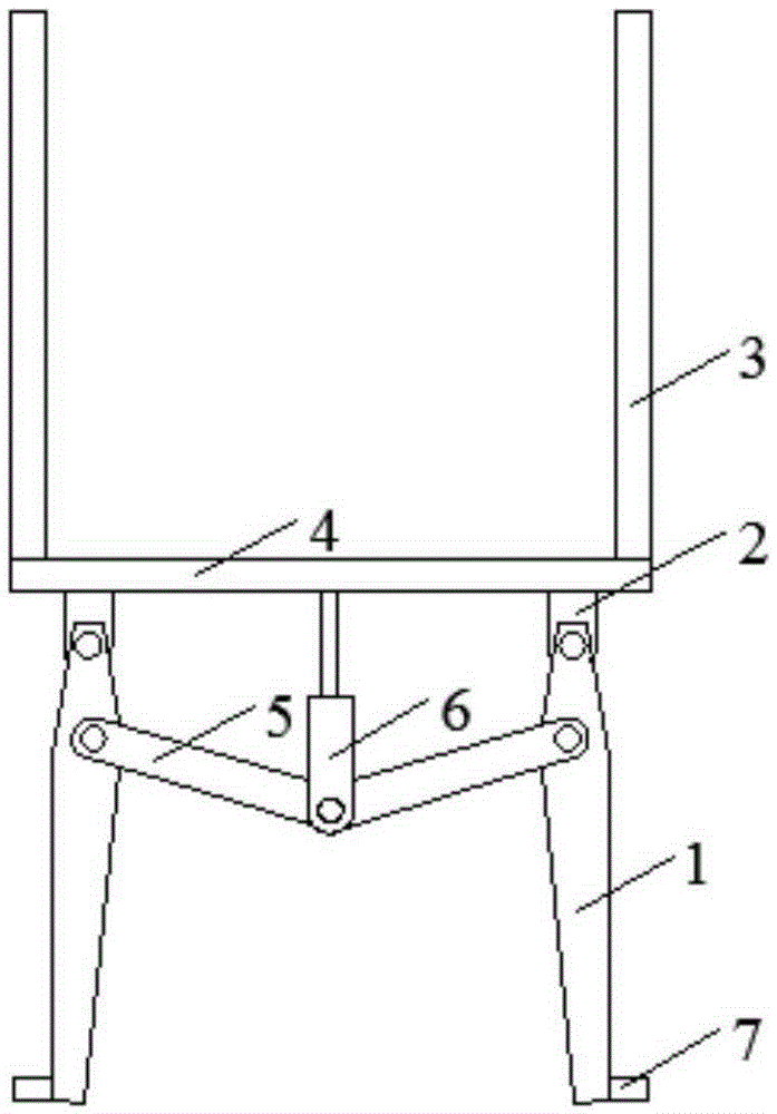
[0015] A tire grabbing device, comprising a movable chuck 1, a chuck seat 2, a lift belt 3, a fixed plate 4, a connecting rod 5, a telescopic rod 6, and a finger-like protrusion 7, the fixed plate 4 is a circular thin plate, and the clamp The head seat 2 is fixed on the bottom surface of the fixed plate 4, the movable chuck 1 and the chuck seat 2 are connected in the form of a rotating pair, one end of the connecting rod 5 forms a rotating pair with the movable chuck, and the other end connects with the bottom of the telescopic rod 6 The end forms a rotating pair, and the telescopic rod 6 is fixed in the middle of the bottom surface of the fixed plate 4, and its length can be extended or shortened as required. When the movable chuck 1 moves to th...


PUM


Abstract

The invention discloses a tire grabbing device, pertaining to the technical field of design of machinery devices. The tire grabbing device comprises movable chucks, chuck seats, elevating strips, a fixed plate, connecting rods, a telescopic rod and finger-shaped protrusions. The fixed plate is a circular thin plate. The chuck seats are fixed on the bottom surface of the fixed plate. The movable chucks are connected with the chuck seats through rotary pairs. One end of each connecting rod and each movable chuck form a rotary pair. The other end of each connecting rod and the bottom end of the telescopic rod form a rotary pair. The telescopic rod is fixed in the middle of the bottom surface of the fixed plate. The length of the telescopic rod can be increased or decreased according to needs. When the movable chucks move to an inner cavity of a tire, the telescopic rod shortens and the connecting rods and connecting ends thereof are pulled to move upwards. The other end of each connecting rod is expanded by each movable chuck such that the tire can be clamped tightly from the inside to the outside. Grabbing operation is achieved. The tire grabbing device has following beneficial effects: the overall device is agile in motion; and clamp force among the movable chucks and the tire is enough great so that the tire can be grabbed reliably and does not fall down.

Description

technical field [0001] The invention relates to the technical field of mechanical device design, in particular to a tire grabbing device. Background technique [0002] Tires are an essential part of various means of transportation, and they may encounter various harsh environments or be scratched by external sharp objects during use, causing damage to the tires. Therefore, mass production of tires is In order to ensure the normal operation of the vehicle is one of the important factors. In the production process of large quantities of tires, the problem of tire movement is often involved. Due to the large size and weight of tires, the traditional manual movement method has high labor intensity and low movement efficiency. When the mobile equipment handles such bulky and heavy parts, it often has problems such as insufficient clamping force, easy to fall during the moving process, complex structure, and low degree of automation. Therefore, a flexible and movable clamp is des...

Claims


Application Information

Patent Timeline
Patent Type & Authority Applications(China)
IPC IPC(8): B65G47/90
Inventor 鲍定胜鲍卫东徐胜
Owner ANHUI SNELL MACHINERY MFG
Why Eureka
Try Eureka