
Guide flow bottom plate

A deflector and bottom plate technology, which is applied in the direction of waterway systems, floors, drainage structures, etc., can solve the problems of hard water accumulation, easy slipping, and slow water launch, so as to speed up water flow, avoid water accumulation, and speed up water flow speed effect

Pending Publication Date: 2017-04-26
平湖市郁洁卫浴有限公司
View PDF9 Cites 3 Cited by
  • Summary
  • Abstract
  • Description
  • Claims
  • Application Information

AI Technical Summary

Problems solved by technology

[0004] The invention solves the problem that the horizontal ground water in the shower room, bathroom, toilet or kitchen is difficult to remove, the water is slow, easy to slip, and the walking safety cannot be ensured.

Method used


Image

  • Guide flow bottom plate
  • Guide flow bottom plate
  • Guide flow bottom plate

Examples


Embodiment 2

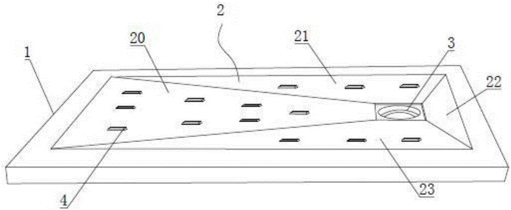
[0028] Embodiment two, such as figure 2 As shown, the first diversion area 20, the second diversion area 21 and the fourth diversion area 23 are respectively provided with a diversion groove 200, a flow groove 210, and a flow groove 230, and one end of the diversion groove is connected with the side plate 1, The other end communicates with the water outlet 3. The diversion groove can disperse the water flow, and at the same time accelerate the speed of the water flow, avoiding the possibility of water accumulation.

Embodiment 3

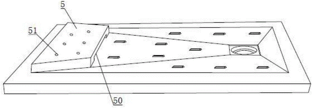
[0029] Embodiment three, such as image 3 As shown, a drain table 5 is provided on the end of the first diversion area 20 close to the side plate 1 . A draining hole 51 is provided on the draining table, and the bottom of the draining table 5 is a hollow structure, and the side wall of the draining table 5 is provided with an opening 50 passing through the first diversion area 20 and the bottom of the draining table. After cleaning, stand on the water draining platform 5, the residual moisture of the soles can be flowed back into the first diversion area 20 by the water draining platform 5, and then flow to the water outlet 3 along the first diversion area 20.

[0030] like Figure 4 As shown, the three sides of the side plate 1 can also be installed with a coaming plate 6, and the coaming plate 6 can ensure that due to the blockage of the sewer, the backflow of sewage does not pollute the wall.


PUM


Abstract

The invention discloses a guide flow bottom plate, comprising side plates, a guide flow plate and a drain hole; the side plates are encircled at four sides of the guide flow plate; the guide flow plate is partitioned into four zones, which are first guide flow zone, a second guide flow zone, a third guide flow zone and a fourth guide flow zone; four sides of the drain hole are encircled by the first guide flow zone, the second guide flow zone, the third guide flow zone and the fourth guide flow zone; the first guide flow zone, the second guide flow zone, the third guide flow zone and the fourth guide flow zone are inclined structure; the high inclined end parts of the first guide flow zone, the second guide flow zone, the third guide flow zone and the fourth guide flow zone are connected with the upper surface of the side plate, and lower end parts are connected with the drain hole, thus the structure of high four sides and low middle part of the guide flow plate is formed. The guide flow bottom plate can avoid waterlog of the bottom plate, and accelerate the water flow speed.

Description

technical field [0001] The invention relates to a bottom plate laid on the ground, in particular to a flow guiding bottom plate. Background technique [0002] In the existing shower room, bathroom, washroom, or kitchen where cleaning is required, when designing this area, water outlets are usually set on the ground, but due to the limitation of the level of the ground itself, the water is slowly launched. The ground is easy to accumulate water, which is not conducive to the discharge of waste water and sewage on the ground, and it is easy to slip. Contents of the invention [0003] The object of the present invention is to provide a floor that can direct the flow of water. [0004] The present invention solves the problem that it is difficult to remove accumulated water on the horizontal ground of a shower room, a bathroom, a toilet or a kitchen, etc., the water is slowly launched, and it is easy to slip, so that walking safety cannot be ensured. [0005] The technical s...

Claims


Application Information

Patent Timeline
IPC IPC(8): E03F5/00E04F15/00
CPCE03F5/00E04F15/00E04F15/02172
Inventor 许建军
Owner 平湖市郁洁卫浴有限公司
Learn More